
EHWD-B
Flat-Bottom Type
Sludge settles in the flat-bottom tank and is removed manually. Typically selected for airflow up to approximately 20,000 m³/h; above this level, manual cleaning is usually impractical.
These industrial wet dust collectors use fan-driven airflow through specially shaped channels, lifting water into a turbulent curtain that washes dust from the air. No scrubbing pump or spray nozzles are needed.
* Combustible-metal applications require dust-specific assessment of water compatibility, water-level protection, hydrogen ventilation and sludge handling.
EHWD-B, C and D share the self-induced wet scrubbing principle. Their main difference is how collected sludge is removed from the water tank.
EHWD-B
Sludge settles in the flat-bottom tank and is removed manually. Typically selected for airflow up to approximately 20,000 m³/h; above this level, manual cleaning is usually impractical.
EHWD-C
A chain scraper removes settled sludge from the tank. One of the main configurations for large-airflow projects.
EHWD-D
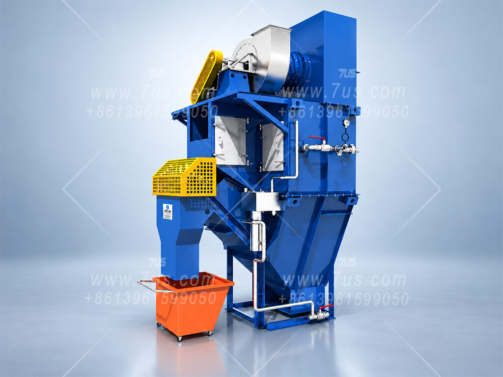
Sludge collects in the lower conical hopper and is discharged by flushing. Another main configuration for large-airflow projects.
Assembled equipment in our workshop. The examples below show the external layout and visible components of each configuration.
EHWD-B
Two views show the assembled collector, top-mounted fan, inspection window and side-mounted control cabinet.
EHWD-C
The assembled unit shows the upper fan platform, access ladder and inclined scraper discharge with a collection trolley.
EHWD-D
The assembled unit shows the top-mounted fan, lower hopper, support frame and side-mounted control cabinet.
This self-induced wet scrubber draws dust-laden fumes into a specially shaped airflow passage. Accelerating air drives vigorous, continuously rolling waves and splashes without a separate water pump or spray nozzles.
Water level and pressure drop. A higher water level can intensify scrubbing but also raises resistance and fan power demand at the same airflow. Typical collector pressure drop is about 1,500–2,000 Pa; under higher-resistance conditions it may approach 3,000 Pa. Actual values depend on the model, airflow and operating water level.
The extraction fan generates negative pressure, drawing dust-laden fumes from the production process through the inlet and into the specially shaped airflow passage.
Air accelerates through the narrow passage of the stationary wave generator and strikes the water surface, raising vigorous, continuously rolling waves and abundant splashes that bring the dust-laden air into close contact with water.
Rolling water and bubbles bring dust-laden air into close contact with water. Captured particles return to the tank with the water and settle as sludge.
After the scrubbing zone, the airstream passes through mist eliminator baffles. Entrained droplets are removed and drain back to the tank before air exits.
In the C type shown, a bottom chain scraper conveys settled sludge toward the discharge point.
Tank water is reused. A float level control opens the make-up water solenoid valve when evaporation or sludge discharge lowers the water level.
B, C and D use the same airflow sizing range. Choose the required total airflow, then select the sludge-removal design according to the application. C and D are the main choices for larger duties; B is usually selected for smaller installations where manual sludge removal is practical.
Sizes 1.5–44 · one independent collector per row
| EHWD size | Airflow (m³/h) | Arrangement | Fan power (kW) |
|---|---|---|---|
| EHWD-1.5 | 2,520–3,024 | 1 collector | 4–5.5 |
| EHWD-2.5 | 4,200–5,040 | 1 collector | 5.5–7.5 |
| EHWD-4 | 6,720–8,064 | 1 collector | 7.5–11 |
| EHWD-6 | 8,000–12,096 | 1 collector | 11–18.5 |
| EHWD-8 | 13,440–16,128 | 1 collector | 18.5–22 |
| EHWD-12 | 20,160–24,192 | 1 collector | 22–37 |
| EHWD-16 | 26,880–32,256 | 1 collector | 37–45 |
| EHWD-20 | 33,600–40,320 | 1 collector | 45–55 |
| EHWD-24 | 40,320–48,384 | 1 collector | 45–55 |
| EHWD-28 | 47,040–56,448 | 1 collector | 55–75 |
| EHWD-32 | 53,760–64,512 | 1 collector | 55–75 |
| EHWD-36 | 60,480–72,576 | 1 collector | 90–110 |
| EHWD-40 | 67,200–80,640 | 1 collector | 90–110 |
| EHWD-44 | 73,920–88,704 | 1 collector | 110–132 |
B is usually selected up to about 20,000 m³/h because its settled sludge is removed manually.
Size 48: single collector · larger sizes: parallel systems
| EHWD size | Airflow (m³/h) | Arrangement | Fan power (kW) |
|---|---|---|---|
| EHWD-48 | 80,640–96,768 | 1 collector | 132–160 |
| EHWD-56 | 94,080–112,896 | 2 × EHWD-28 | 160–200 |
| EHWD-64 | 107,520–129,024 | 2 × EHWD-32 | 185–250 |
| EHWD-72 | 120,960–145,152 | 2 × EHWD-36 | 200–280 |
| EHWD-80 | 134,400–161,280 | 2 × EHWD-40 | 250–355 |
| EHWD-96 | 161,280–193,536 | 2 × EHWD-48 | 280–400 |
| EHWD-108 | 181,440–217,728 | 3 × EHWD-36 | On request |
| EHWD-120 | 201,600–241,920 | 3 × EHWD-40 | On request |
| EHWD-132 | 221,760–266,112 | 3 × EHWD-44 | On request |
| EHWD-144 | 241,920–290,304 | 3 × EHWD-48 | On request |
| EHWD-160 | 268,800–322,560 | 4 × EHWD-40 | On request |
| EHWD-176 | 295,680–354,816 | 4 × EHWD-44 | On request |
| EHWD-192 | 322,560–387,072 | 4 × EHWD-48 | On request |
| EHWD-240 | 403,200–483,840 | 5 × EHWD-48 | On request |
The listed parallel arrangements show one matching combination. Fan power from size 108 onward is specified on request.
Model examples: EHWD-8C = Size 8, Type C; EHWD-8D = Size 8, Type D. The final letter identifies the configuration.
Airflow and fan power values are for preliminary selection only. Final selection depends on the required airflow and total system resistance.
For higher total airflow, the inlet main splits into branch ducts feeding separate collectors. Their outlet branches return to a shared outlet main. The collectors remain complete, independent machines.
The listed fan power ranges are for preliminary reference. Final motor selection depends on total system airflow and pressure losses. The collector itself typically has a pressure drop of about 1,500–2,000 Pa; this is not the full fan system pressure.
Two views of an example multi-unit arrangement. Configuration and unit count are project-specific.
Application examples and configurations for specific process conditions.
When blasting oil-coated steel, heat can generate oil mist that clogs cartridge or bag filters. Hot particles and sparks can also ignite dry filter media. Blasting aluminium, magnesium or titanium requires additional protective measures tailored to the dust and process.
Above the built-in mist eliminator, an optional F9 prefilter and a further optional HEPA filter stack directly on the collector to form one integrated unit. In this configuration, HEPA is fitted only after F9: the F9 prefilter reduces the particle load on the HEPA filter, which captures the remaining fine particles.
Fine dust from these metals can present fire and explosion hazards. Depending on the metal, alloy and process conditions, contact with water can also release hydrogen. This application combines wet dust capture with continuous sludge removal and dedicated hydrogen venting.
Installed inside the workshop, a large C-type self-induced wet dust collector serves multiple grinding stations on this automotive wheel production line. Branch ducts connect the stations to a common extraction main, carrying grinding dust to the collector for wet separation.
The C-type chain scraper continuously removes settled sludge during operation. The collector and ductwork are arranged around the production line, with space for access and maintenance.
Collection zones must be defined by dust type, process and fire compartment. Ferrous grinding dust must be collected separately from aluminium or magnesium alloy dust, using independent ductwork and collectors without interconnections between these systems. System zoning and configuration must meet the applicable local safety requirements.
A 30,000 m³/h C-type self-induced wet dust collector serves a turbocharger turbine housing foundry, treating oil-laden fumes and particulate emissions from the casting process.
A 40,000 m³/h D-type self-induced wet dust collector serves this mineral crushing installation. Fog cannons and dry-fog sprays suppress dust in the workshop and at key dust-generating points. The extracted air therefore carries moisture and water droplets, making wet collection a suitable choice.
A D-type self-induced wet dust collector handles hot, moisture-laden fumes from these processes, with a separate wastewater treatment system for the large slurry load.
A 50,000 m³/h EHWD-32DFH wet dust collector treats lead-containing fumes, particulate matter and mould-release emissions from melting, casting and demoulding lead-antimony alloy battery grids.
Oily, moist or hot dust? Consider wet collection.
Additional application areas for assessment, with B, C or D selected to suit airflow, dust properties and sludge handling.
Belt transfers · loading · screening
Wet dust collection can be considered for coal-handling points, particularly where spray suppression creates moist dust. Selection must address coal wettability, sludge handling and combustible-dust hazards.
Batching · mixing · material transfer
For wettable ceramic and mineral dust from powder handling, mixing and transfer points. Water-based capture offers an option where humidity or sticky deposits complicate dry filtration.
Trimming · finishing · powder handling
An option for wettable dust from rubber and plastics processing, including sticky or oil-laden particulate. Material compatibility and the resulting sludge determine the collection arrangement.
Weighing · blending · packaging
Wet collection may suit selected food-powder and ingredient-handling duties. Product characteristics, hygiene needs and wastewater handling must be considered together.
Bag tipping · charging · material transfer
Wet collection can be considered for water-compatible chemical powders, including selected dust from silica and silicate production. Dust chemistry, circulating-water pH and sludge handling are assessed for each process.
Dryers · heated mixing · moist exhaust
Consider wet collection where particulate is carried in hot, humid process air. Gas cooling and circulating-water temperature control are selected for the actual heat load.
Combustible dust: Wet collection requires a dust-specific assessment of water compatibility, ignition and explosion hazards, and any gas generation. Protective measures are selected for the complete system.
EHWD-S is a compact self-induced wet dust collector for connection to a dust source by ductwork. It can also serve a separate grinding table. EHWD-V brings the grinding table and wet collector together in one workstation. Other airflow capacities and grinding table sizes can be designed to suit specific applications.
The fan draws dust-laden air through the inlet and into the wet collection zone. Airflow raises a turbulent water wash that captures particles; entrained droplets are then separated before the air exits. No separate scrubbing pump or spray nozzles are required.
| Model | Airflow (m³/h) | Fan motor (kW) |
|---|---|---|
| EHWD-S2 | 1,700–2,500 | 3–4 |
| EHWD-S3 | 2,500–3,500 | 4–5.5 |
| EHWD-S4 | 3,500–5,000 | 5.5–7.5 |
| EHWD-S5 | 5,000–6,000 | 11 |
EHWD-S · STANDALONE
The standalone collector connects to a machine or capture point through ductwork. The compact body integrates the wet collection stage and extraction fan.
EHWD-S · SEPARATE TABLE
The grinding table and wet collector are separate pieces of equipment connected by ductwork. Their positions can be arranged around the available workspace.
EHWD-V places the grinding surface directly in front of the wet collector. Dust is captured at the work area and carried into the self-induced water wash within the same equipment.
Three standard work surface sizes provide a starting point for selecting a workstation around the workpiece and available floor space.
| Model | Work surface (D × W, mm) | Airflow (m³/h) | Fan motor (kW) |
|---|---|---|---|
| EHWD-V2 | 600 × 600 | 2,000–3,000 | 4–5.5 |
| EHWD-V4 | 600 × 1,200 | 3,000–6,000 | 7.5–11 |
| EHWD-V6 | 600 × 1,800 | 6,000–9,000 | 15–18.5 |
EHWD wet dust collectors can be specified for the dust, airflow, installation layout and discharge requirements of each project. The options below are selected as part of the overall system design.
Automatic make-up water and low-water protection help maintain the operating water level required for self-induced scrubbing.
Select manual cleaning for smaller B-type duties, chain scraper discharge for C-type units, or hopper flushing for D-type units according to sludge load and maintenance access.
A cyclone separator or Venturi spray stage can be added upstream when the process calls for pre-treatment before wet collection.
Where finer downstream filtration is required, an F9 prefilter and H14 HEPA stage can be arranged after mist elimination. The after-filter configuration depends on the process and discharge target.
Contact surfaces, water treatment, settling and recirculation arrangements are selected for the dust chemistry, sludge properties and operating temperature.
Fan layout, motor, variable-frequency drive and control cabinet can be specified around the required airflow, system resistance and site power supply.
For combustible metal dust, the full collection system is assessed for material-water compatibility, hydrogen management and application-specific protective measures.
Quick answers to common questions about self-induced wet collection, model selection and maintenance.
No. The fan-driven air stream lifts water through the collector’s internal passage to create the primary washing action. An optional upstream Venturi spray stage is a separate system configuration.
Wettable, sticky or moisture-laden dust may be suitable. For aluminum, magnesium, titanium and other combustible metal dusts, the dust and complete system must be assessed for water compatibility and protective measures.
EHWD-S is a compact collector connected to a dust source by ductwork and can also serve a separate grinding table. EHWD-V integrates the grinding surface and wet collector into one workstation.
The model tables provide starting ranges. The selected airflow and fan motor depend on the dust source, capture layout, ductwork and total system resistance.
The arrangement follows the dust load and machine configuration: manual cleaning, chain scraper discharge or hopper flushing can be specified where appropriate.
Maintain the operating water level, check the water circuit and mist eliminator, and remove accumulated sludge. The cleaning schedule depends on dust loading and operating hours.
Share the dust type, required airflow, site layout and available power supply. We can review an EHWD configuration for your application.