7US 7US Industrial dust collector since 1994

Vertical Cartridge Dust Collectors

Modular vertical cartridge dust collectors with front-access, drawer-like cartridge replacement, eccentric cam clamping and automatic pulse-jet cleaning.
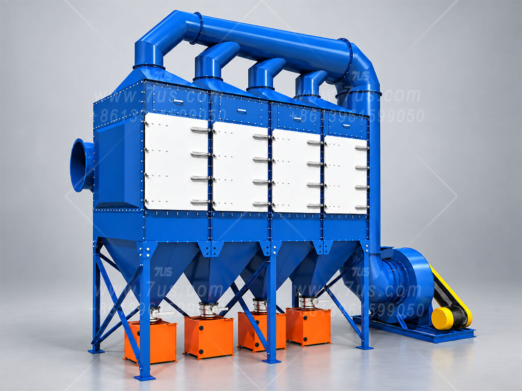
  • Vertical cartridge arrangement
  • Automatic pulse-jet cleaning
  • Front-access, drawer-like cartridge replacement
  • Single or multi-module configurations
7US DHC vertical cartridge dust collector modular series
Vertical Cartridge ArrangementCartridges installed vertically inside the filter chamber
Front-Access ReplacementDrawer-like slide-out cartridge maintenance
Eccentric Cam ClampingSecure mechanical cartridge compression
Modular ConstructionFlexible capacity expansion

Front-Access Slide-In Cartridge System

The cartridges are installed vertically below the tube sheet, but routine replacement is performed entirely from the front of the collector. A guided hanging structure, standardized cartridge top plate and eccentric cam clamping mechanism allow each cartridge to be pushed into position in a drawer-like motion without dismantling the clean-air chamber above.
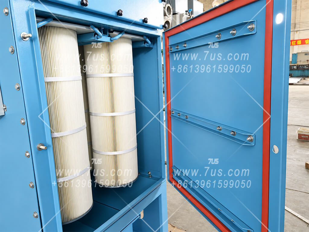
Front-access DHC vertical cartridge dust collector with service door open and cartridges installed vertically
Front-access maintenanceOpen the front service door to reach the vertical cartridges directly from the filter chamber side.
DESIGNED AROUND ROUTINE MAINTENANCE

No Clean-Air Chamber Disassembly

Cartridge replacement does not require removal of the venturis or pulse pipes above the tube sheet. The operator works from the front service opening, releases the eccentric cam clamping mechanism, slides the cartridge along the guide structure, and locks it back into its designed position after replacement.

Front access: no overhead cartridge lifting space is required for routine replacement.
Clean-air side remains untouched: venturis and pulse-cleaning pipes stay in place.
Guided positioning: the cartridge top plate follows the fixed guide structure into its designed location.
Eccentric cam clamping: once the lever is raised into the clamped position, the eccentric geometry applies secure cartridge compression and remains mechanically stable without continuous external force.
STEP 01Open the Front DoorAccess the cartridge chamber directly from the service side of the collector.
STEP 02Release the Cam ClampLower the eccentric cam clamping mechanism to remove the cartridge compression force.
STEP 03Slide the CartridgeHang the steel top plate on the guide structure and push or pull the cartridge in a drawer-like motion.
STEP 04Clamp & AlignRaise the cam lever to lock the cartridges at the designed tube-sheet and pulse-cleaning centerlines.

Structure You Can See

These production photographs show the clamping detail, the untouched clean-air-side components above the tube sheet, and the fixed geometry that keeps each cartridge centered below its corresponding opening.
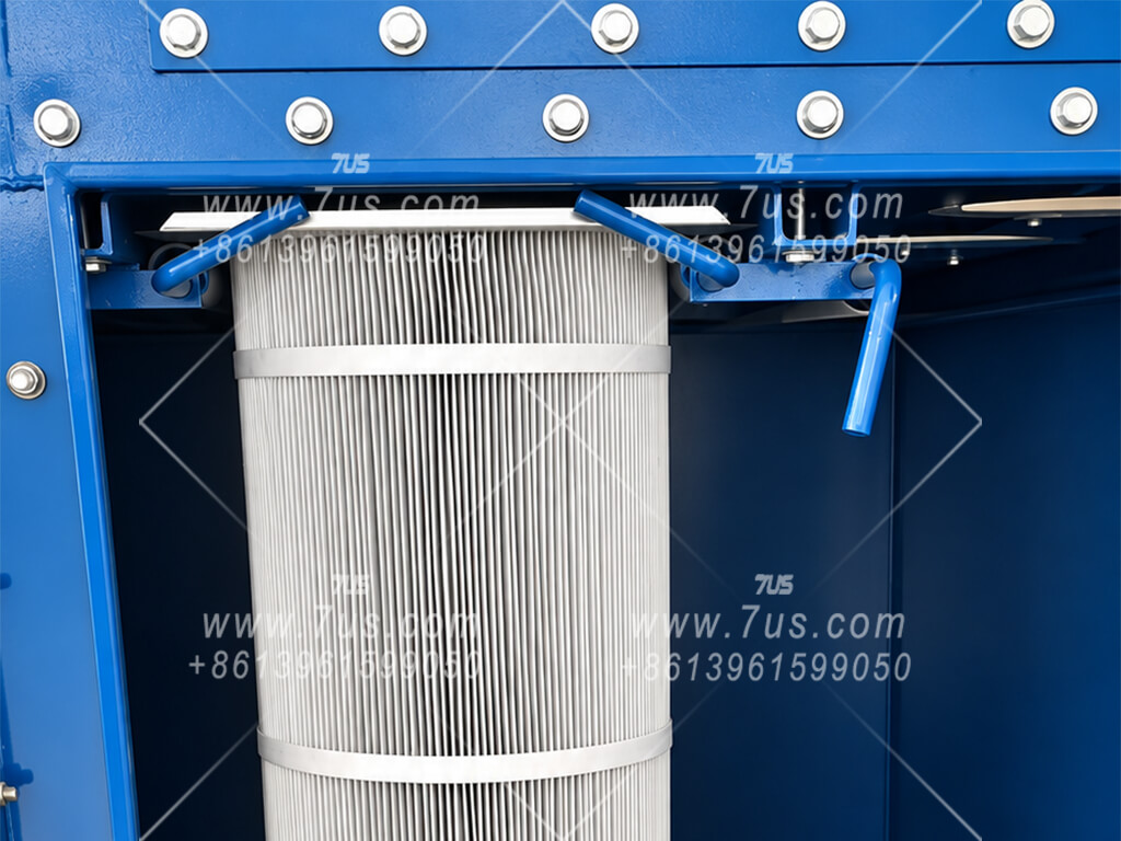
Eccentric cam clamping mechanism for a DHC vertical filter cartridge
Eccentric Cam ClampingThe eccentric cam mechanism clamps the cartridge securely after it is slid into position.
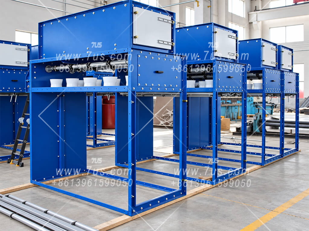
Clean-air chamber of a DHC vertical cartridge dust collector with venturis and pulse pipes
Clean-Air Side Stays AssembledVenturis and pulse-cleaning pipes remain installed during routine cartridge replacement.
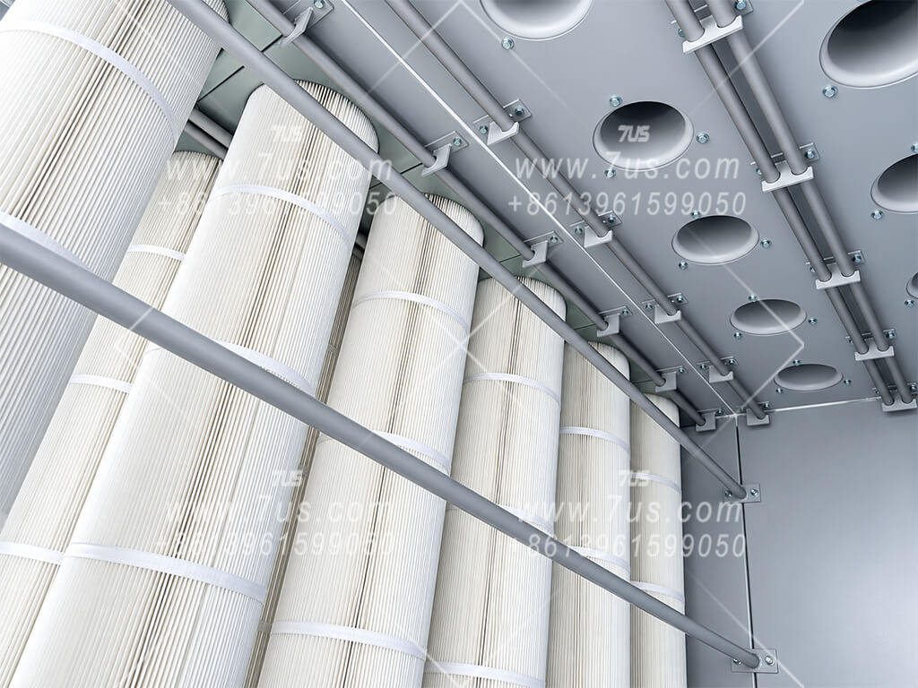
Vertical filter cartridges aligned beneath DHC tube-sheet openings
Designed-In AlignmentGuide geometry positions the cartridge centerline directly below the corresponding tube-sheet opening and pulse-cleaning centerline.
Open the door. Release the cam. Slide the cartridge out.
The maintenance advantage comes from the installation architecture itself. The cartridges remain vertical in operation, while the front-access slide-in structure avoids the overhead clearance and clean-air-chamber disassembly associated with top-loading replacement methods.

Lower-Inlet Airflow & Pre-Separation

The vertical cartridge layout is designed so dust-laden air can enter below the cartridge section, where the larger internal cross-section reduces velocity before the finer dust reaches the filter media. This creates a useful settling and airflow-conditioning zone ahead of filtration.
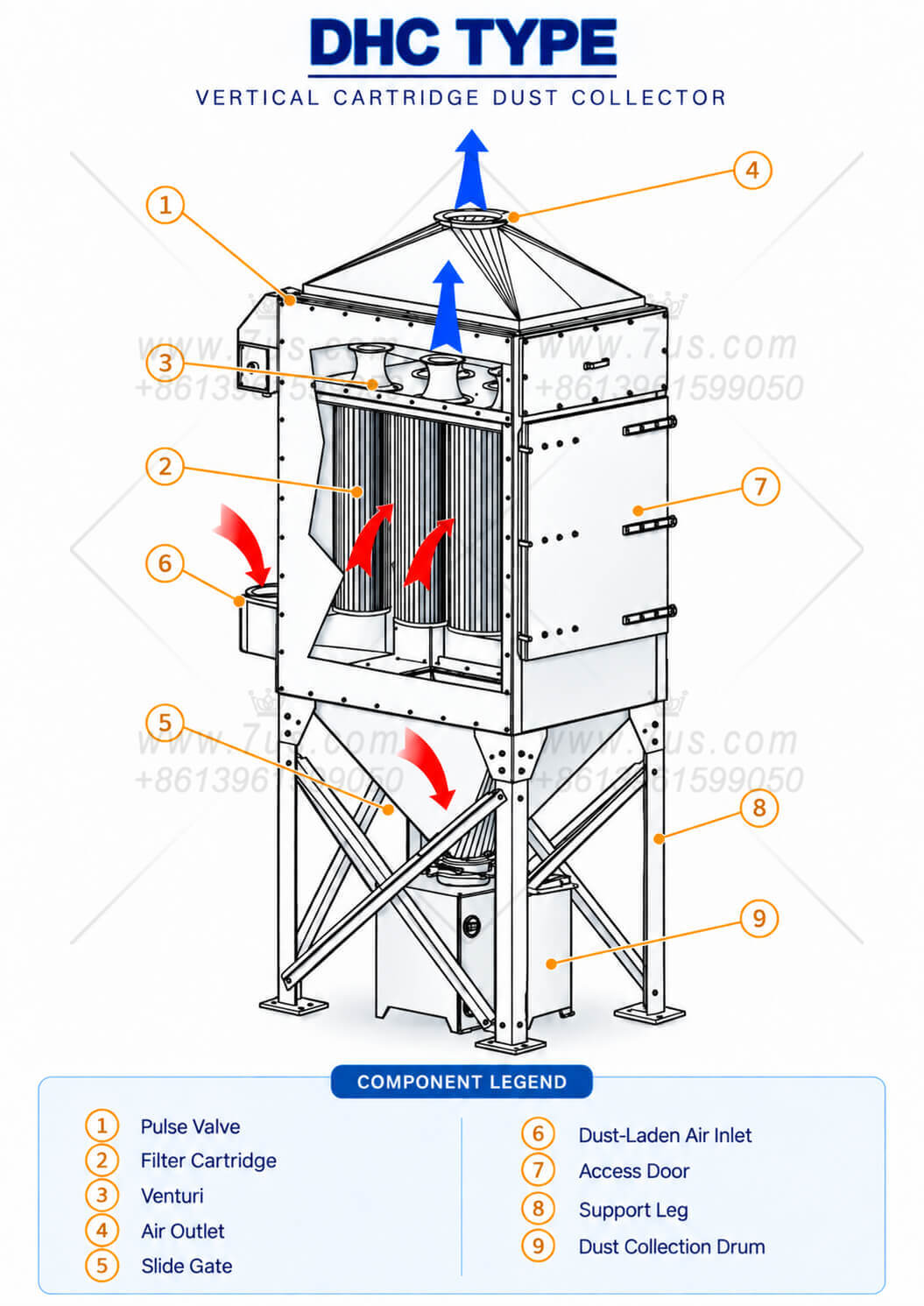
DHC vertical cartridge dust collector airflow diagram with lower inlet, filter cartridges and upper clean-air outlet
AIRFLOW DESIGNED AROUND THE FILTER CARTRIDGES

Slow the Dust Before It Reaches the Filter Media

High-velocity dust-laden air is introduced below the cartridges. Once it enters the larger collector body, the available flow area increases and air velocity drops, reducing direct impact on the filter media and giving heavier particles an opportunity to fall toward the hopper before the finer fraction moves upward to the cartridges.

01 · LOWER INLETVelocity ReductionDust-laden air enters beneath the cartridge zone. The sudden increase in cross-sectional area lowers the local air velocity.
02 · PRE-SEPARATIONHeavier Particles Settle FirstCoarser particles lose momentum and tend to fall into the hopper, while lighter fine dust remains suspended and travels upward.
03 · FILTRATION & CLEANINGFine Dust Reaches the CartridgesFine dust is captured on the outer cartridge surface. Differential-pressure or timed control then triggers pulse-jet cleaning so released dust falls into the hopper.
Core design principle: the preferred airflow path is lower inlet → conditioning / settling zone → vertical cartridge filtration → upper clean-air chamber. Depending on the dust concentration and particle characteristics, additional pre-separation equipment may still be required.

Flexible Inlet & Outlet Arrangement

The airflow principle remains the same, while inlet and clean-air outlet positions can be adapted to site space, duct routing and system layout. Large modular systems normally benefit from a dedicated lower inlet / air-distribution section; compact integrated units may use side-entry arrangements with internal baffles where required.
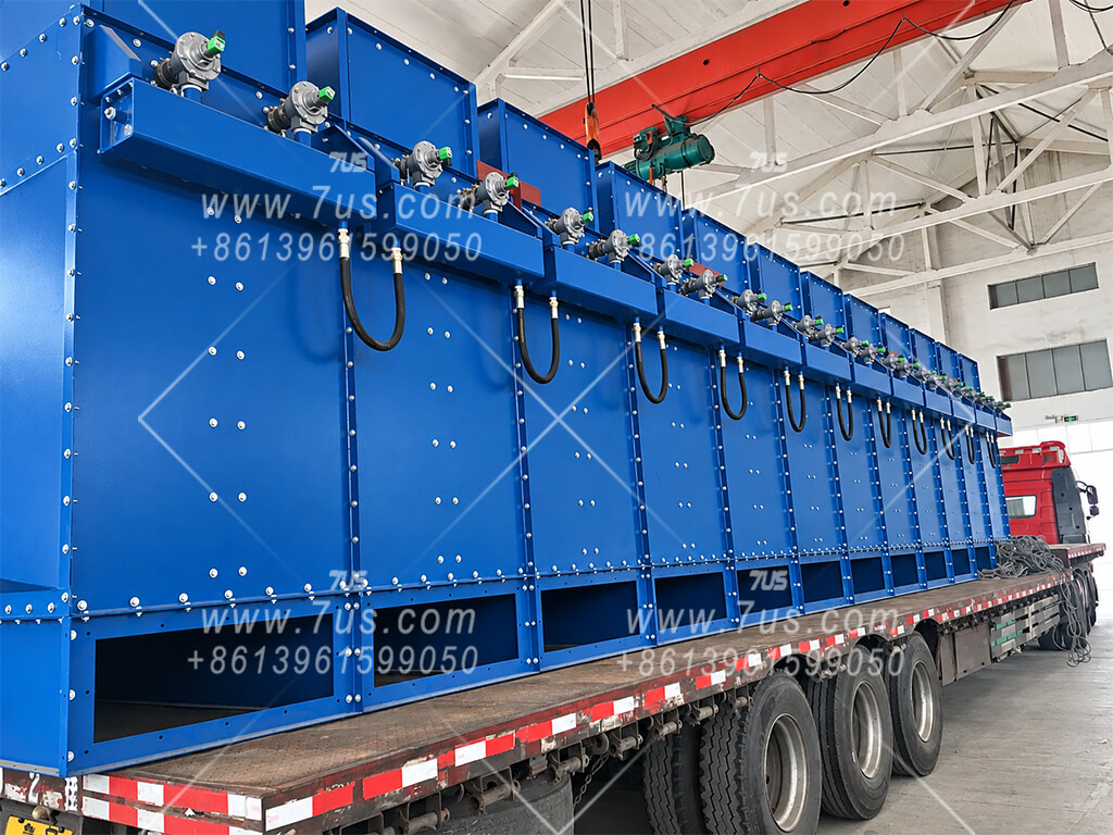
Rear view of a modular DHC vertical cartridge dust collector with lower inlet air-distribution section
Inlet Conditioning & Air Distribution SectionLarge modular collectors can use a dedicated lower inlet section beneath the cartridge zone to distribute incoming airflow, reduce velocity and support pre-settling before fine filtration.
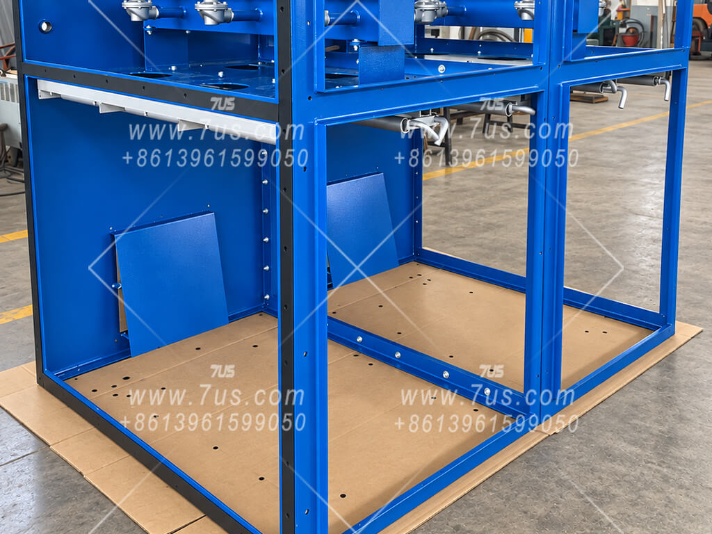
Compact DHC vertical cartridge dust collector frame with side inlet and internal deflector baffle
Side Inlet with Internal Deflector BaffleFor compact or height-limited layouts, a side-entry inlet can be used. An internal baffle redirects and disperses the incoming flow so dust does not impinge directly on the cartridges.
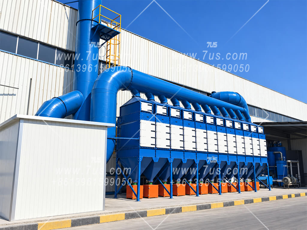
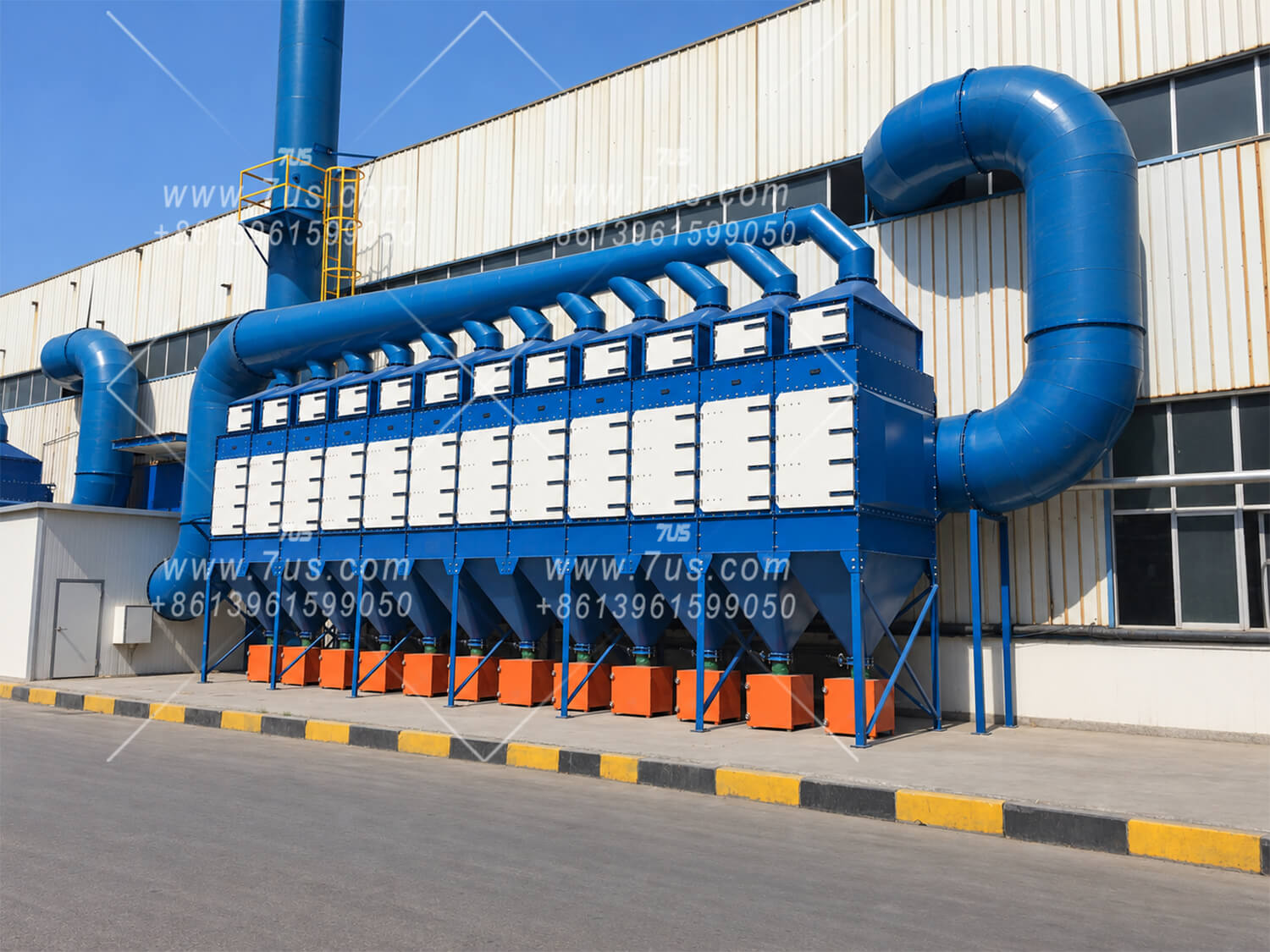
Multi-module DHC vertical cartridge dust collector installation with common upper clean-air manifold
Typical Large-System Airflow LayoutA completed multi-module system shows how individual modules can share a common upper clean-air manifold while retaining the same lower-inlet, upward-filtration airflow principle.
Keep the airflow principle. Adapt the duct connections to the site.
Inlet and outlet positions are project-configurable. Lower-side, side-entry and other connection arrangements can be designed around available space and duct routing. The important part is maintaining controlled airflow distribution and avoiding direct high-velocity dust impact on the filter media.

Why Cartridge Orientation Matters

Inclined cartridges are a proven industrial arrangement, but their upper-facing surface can still provide an area where released dust may settle again after pulse cleaning. A fully vertical cartridge removes this upward-facing dust-resting surface.
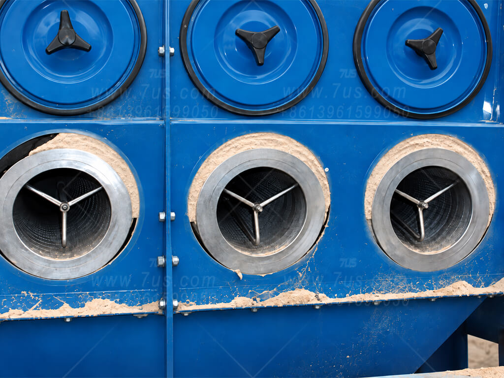
Inclined cartridge dust collector after service showing dust accumulation on upward-facing cartridge surfaces
REAL OPERATING CONDITION — INCLINED CARTRIDGES

Released Dust Can Settle Again on Upward-Facing Surfaces

The photograph shows an actual inclined-cartridge collector after service. Dust behavior varies with particle characteristics, loading and pulse-cleaning conditions, but the inclined geometry still leaves an upper-facing cartridge surface where part of the released dust can remain or re-settle.

Upward-facing cartridge surface An inclined cartridge still presents a surface on which released dust can rest after cleaning.
Re-settling depends on the dust The extent varies with particle size, cohesiveness, dust loading and pulse-cleaning conditions.
Accumulation can increase cleaning demand Persistent deposits can reduce effective use of part of the media surface and may require more frequent cleaning or maintenance.
Vertical orientation removes the upward-facing dust-resting surface. Released dust can move downward more directly under gravity, complementing the lower-inlet and pre-separation airflow principle described above.

How to Select a DHC Vertical Collector

Define the duty. Calculate the filter area. Then fit it to the site. Select suitable media and design filtration velocity for the dust and operating conditions. Use the required airflow to calculate area, then choose cartridge length and module arrangement to suit the available space.

  1. 01Assess the DutyDust properties, inlet concentration and operating conditions.
  2. 02Select Media & VelocityChoose suitable filter media and a design filtration velocity.
  3. 03Calculate Filter AreaUse the required airflow and selected velocity.
  4. 04Check Site SpaceHeight, depth, width and front maintenance access.
  5. 05Configure the CollectorSelect cartridge length, base module and module quantity.
04.1

Start with the Required Filter Area

A model number is not a fixed airflow rating. The design filtration velocity must be selected for the duty before the required filter area is calculated.

Confirm the Dust & Operating Conditions

Review the dust type and inlet concentration, temperature, moisture and any corrosive or combustible characteristics. Confirm the filtration duty and required airflow before choosing the media and design filtration velocity.

Process / dust typeDust concentrationOperating conditionsRequired airflow
Required effective filter area
A =

Filter area = airflow ÷ (60 × design filtration velocity)

A · area, m²Q · airflow, m³/hv · velocity, m/min
Reference basis: 7US polyester cartridges at 1.0 m/min. This is a preliminary calculation basis for normal dust concentrations, not a universal value. The design velocity must be confirmed for the actual duty.
04.2

Configure Height, Depth & Width

Once the area requirement is known, choose how to accommodate it. Cartridge length, cartridges per module and the number of side-by-side modules provide three different layout choices.

Height · cartridge length

Use the Available Height

Longer cartridges provide more area per cartridge. Match the housing height to the selected length and retain the lower inlet and settling space.

Depth · cartridges per row

Choose the Base Module

Each module has two front-to-back cartridge rows. More cartridges in each row require a deeper module.

Width · module quantity

Combine Modules Side by Side

Use more modules to provide additional area, or combine shallower modules where site depth is restricted but width is available.

Standard module

DHC4

4 cartridges / module

2 rows × 22 cartridges front to back in each row

Standard module

DHC6

6 cartridges / module

2 rows × 33 cartridges front to back in each row

Standard module

DHC8

8 cartridges / module

2 rows × 44 cartridges front to back in each row

Standard module

DHC10

10 cartridges / module

2 rows × 55 cartridges front to back in each row

Project-specific

DHC12

12 cartridges / module

2 rows × 66 cartridges front to back in each row

Gold edge = front maintenance side. Top-view cartridge-position schematics only; not dimensional or fabrication drawings. DHC12 is a project-specific option subject to layout and shipping review.
04.3

Same Filter Area. Different Layouts.

With the same cartridge length, media and effective area per cartridge, different module combinations can provide the same total filter area. Select the layout that fits the site.

Same 1000 mm cartridges

1 × DHC8 or 2 × DHC4

112 m²in either layout
One DHC8 module compared with two DHC4 modules Top-view arrangement schematic. The left option has two rows of 4 cartridges. The right option has two side-by-side modules, each with two rows of 2 cartridges. Both options contain 8 cartridges. Front maintenance access is at the bottom. Not to scale.1 × DHC82 × DHC4ORDeeper single moduleShallower, wider layout
8 cartridges × 14 m² = 112 m²

Use one DHC8 where depth is available. Where depth is restricted but width is available, place two DHC4 modules side by side.

Same 1000 mm cartridges

1 × DHC12 or 2 × DHC6

168 m²in either layout
One DHC12 module compared with two DHC6 modules Top-view arrangement schematic. The left option has two rows of 6 cartridges. The right option has two side-by-side modules, each with two rows of 3 cartridges. Both options contain 12 cartridges. Front maintenance access is at the bottom. Not to scale.1 × DHC122 × DHC6ORDeeper single moduleShallower, wider layout
12 cartridges × 14 m² = 168 m²

Use one DHC12 where depth and transport permit. Two DHC6 modules provide an alternative when a shallower layout or different shipping arrangement is needed.

Front access at the bottom of each plan. Layouts are schematic, not to scale. Equal filter area does not imply identical overall dimensions, pressure loss, cost or transport requirements.
04.4

More Area Without More Cartridges

The same DHC8 module concept can use eight Ø324 mm cartridges of different lengths. At the confirmed media specification, longer cartridges increase area without adding cartridges.

Most common

1000 mm

14 m² / cartridge

112 m² total / DHC8Baseline area
Common

1200 mm

16.8 m² / cartridge

134.4 m² total / DHC820% more area
Project-specific

1500 mm

21 m² / cartridge

168 m² total / DHC850% more area
Length is a design choice, not a drop-in upgrade. A longer cartridge requires a compatible housing and adequate inlet-conditioning, settling and maintenance space. 1000 and 1200 mm are the most commonly selected lengths. 660 mm, 1500 mm and custom lengths are available for project-specific requirements; 7US manufactures the cartridges in-house.
04.5

From Airflow to a Practical Layout

This example demonstrates the selection method. It assumes that the process has already been assessed and a design filtration velocity of 1.0 m/min has been selected.

Worked example · preliminary area check

One Airflow Requirement. Three Possible Layouts.

Required airflow: 6,000 m³/h
Selected design filtration velocity: 1.0 m/min

6,000 ÷ (60 × 1.0) = 100 m²Required filter area for this illustrative calculation
A · one deeper module

1 × DHC8

8 cartridges × 14 m²
1000 mm cartridge length

112 m²

A single-module option where sufficient front-to-back depth is available.

B · two shallower modules

2 × DHC4

2 × 4 cartridges × 14 m²
1000 mm cartridge length

112 m²

A side-by-side arrangement where depth is restricted and width is available.

C · fewer, longer cartridges

1 × DHC6

6 cartridges × 16.8 m²
1200 mm cartridge length

100.8 m²

A longer-cartridge option where the required housing height can be accommodated.

All three meet the calculated area requirement. Choose the layout that suits the site, then complete the final engineering checks.
Scaling up · the same selection method

50,000 m³/h: Two Modular Options

Assuming a confirmed design velocity of 1.0 m/min:50,000 ÷ (60 × 1.0) ≈ 833.3 m²

A · 6 × DHC10 modules · 1000 mm cartridges

DHC10-6010

60 cartridges × 14 m² = 840 m²
Six modules combined side by side.

B · 5 × DHC10 modules · 1200 mm cartridges

DHC10-5012

50 cartridges × 16.8 m² = 840 m²
Longer cartridges allow one fewer module.

Both provide 840 m² → reference airflow of 50,400 m³/h at 1.0 m/min.
Equal filter area, different height and width requirements. These are preliminary area-based options, not fixed airflow ratings or final selections.
Before final selection: confirm overall dimensions, front service clearance, inlet and hopper arrangement, pulse cleaning, fan/system pressure and shipping. Recalculate the required area if the design filtration velocity changes.

Standard Module Reference Data

7US polyester-based Ø324 mm cartridges. Reference airflow = total filter area × 1.0 m/min × 60. Values below are for one base module, not a fixed rating for every duty.

Base moduleCartridges
per module
1000 mm · 14 m² / cartridge1200 mm · 16.8 m² / cartridge
Total area (m²)Reference airflow (m³/h)
at 1.0 m/min
Total area (m²)Reference airflow (m³/h)
at 1.0 m/min
DHC44563,36067.24,032
DHC66845,040100.86,048
DHC881126,720134.48,064
DHC10101408,40016810,080
DHC12*1216810,080201.612,096
Swipe horizontally to view all reference columns →
* DHC12 is project-specific. DHC4–DHC10 are the preferred standard modular range for export planning; actual packed dimensions must still be checked. DHC12 requires suitable transport arrangements, such as flat-rack shipment where applicable.
Areas shown apply to this 7US polyester cartridge specification. Media characteristics and pleat count, depth and arrangement together determine the effective filter area. Alternative media can be reviewed for specific duties, subject to cartridge dimensions and confirmed effective area.

How to Read the Model Code

DHC6 and DHC10 identify base modules. A complete collector code also includes the total cartridge count and cartridge length code.

After the first hyphen: total count + two-digit length code. In this block, the last two digits identify cartridge length. All preceding digits give the total cartridge count—even for a single module.
Single-module example
DHC6-612
DHC66 cartridges
per base module
66 cartridges total
= 1 × DHC6 module
121200 mm
cartridge length
Multi-module example
DHC10-5015
DHC1010 cartridges
per base module
5050 cartridges total
= 5 × DHC10 modules
151500 mm
cartridge length
Length codes: 10 = 1000 mm · 12 = 1200 mm · 15 = 1500 mm · 66 = 660 mm. Custom-length codes are confirmed for each project; do not infer the length from an unlisted code.
Additional filtration: a suffix follows the main code, for example DHC10-1015-3H for a HEPA configuration, or DHC10-1015-3CH for HEPA + activated carbon. The exact additional filtration specification is confirmed with the project.
Let 7US Review Your Selection

Send the dust/process details, inlet concentration, required airflow and available height × width × depth. Include temperature, moisture, corrosive components and any explosion-protection requirements where applicable.

Discuss Your Selection

Configure the DHC Around the Project

The DHC filtration module is only one part of the final system. Filter media, material, dust discharge, fan package, electrical standard and safety components are selected around the actual dust duty, layout and destination requirements.

01 · Filter Cartridges

Media & Surface Treatment

Polyester cartridge filters are the standard DHC selection basis. Surface and safety functions are added only where the duty requires them.

  • Polyester filter cartridges
  • PTFE membrane option
  • Antistatic construction
  • Flame-retardant media option
  • Cartridge length and effective area confirmed for the duty
02 · Material & Construction

Collector Material & Structural Customization

The collector body can be manufactured in different materials and structural specifications to suit corrosion conditions, process requirements and customer standards.

  • Q235 carbon steel
  • SS304 stainless steel
  • SS316L stainless steel
  • Customer-specified coating color
  • Plate thickness can be customized for special service conditions
  • Reinforcement and structural strengthening can be customized as required
03 · Hopper Configuration

Collection Volume & Hopper Form

Hopper form is selected around the dust loading, required discharge interval and overall module arrangement.

Individual Hopper
  • Low-profile hopper for lower dust loading
  • Deeper hopper for higher collection volume
Common Hopper
  • Boat-type hopper can serve multiple modules
04 · Dust Discharge

Discharge Valve & Screw Conveyor

The discharge method is matched to the dust characteristics, hopper arrangement and collection frequency.

  • Manual slide gate
  • Manual butterfly valve
  • Motorized rotary airlock valve
  • Screw conveyor for multi-module collectors
05 · Pulse Cleaning

Pulse-Jet Cleaning System

Cleaning hardware and control logic are selected together with the cartridge configuration and operating conditions.

  • Pilot-operated valves with a centralized solenoid valve box
  • Integrated solenoid-operated pulse valves
  • Pulse interval and duration adjustable by pulse controller or PLC
  • Valve and control component brands can be specified
06 · Fan & Electrical Control

Fan, Motor & Control Cabinet

Fan / Motor
  • Collector body supplied separately or with a configured fan package
  • Fan brand and motor brand can be specified
  • Voltage and 50 / 60 Hz frequency configured for the destination
Electrical Control
  • Electrical component brand can be specified
  • PLC, HMI / touchscreen and VFD options
  • Differential-pressure-based control available where required
07 · Safety & Access

Explosion Protection, Safety & Maintenance

Safety components and maintenance access are evaluated around the actual dust, installation environment and local project requirements.

  • Explosion vent panel
  • Flameless explosion venting device
  • Explosion-proof motor and electrical cabinet
  • Spark arrestor / spark trap
  • Maintenance platform or access arrangement as required
Explosion-protection items are configurable components for project requirements. Final compliance scope and component certification should be confirmed for the actual application and destination market.

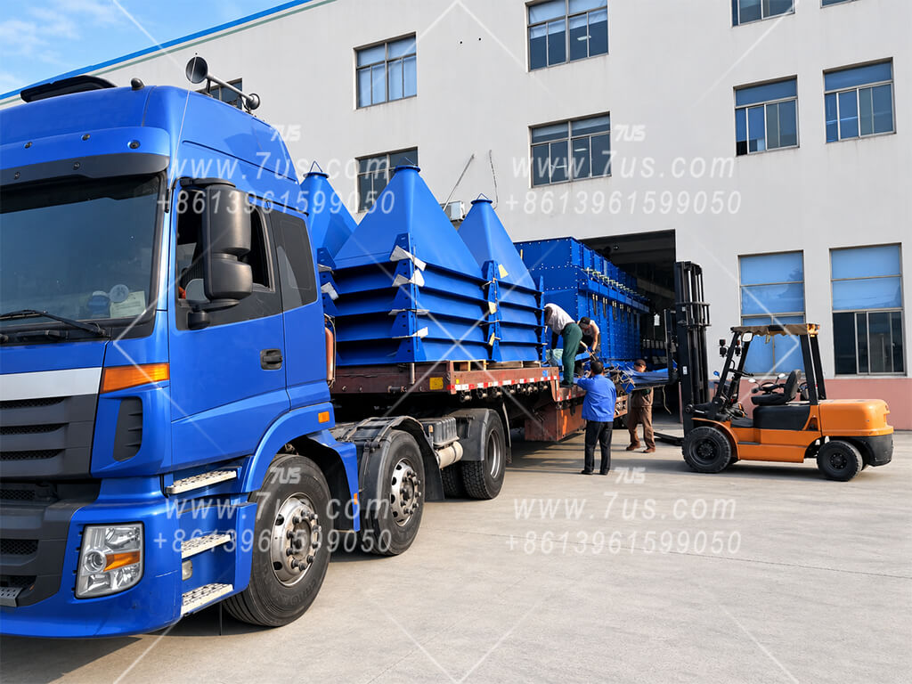
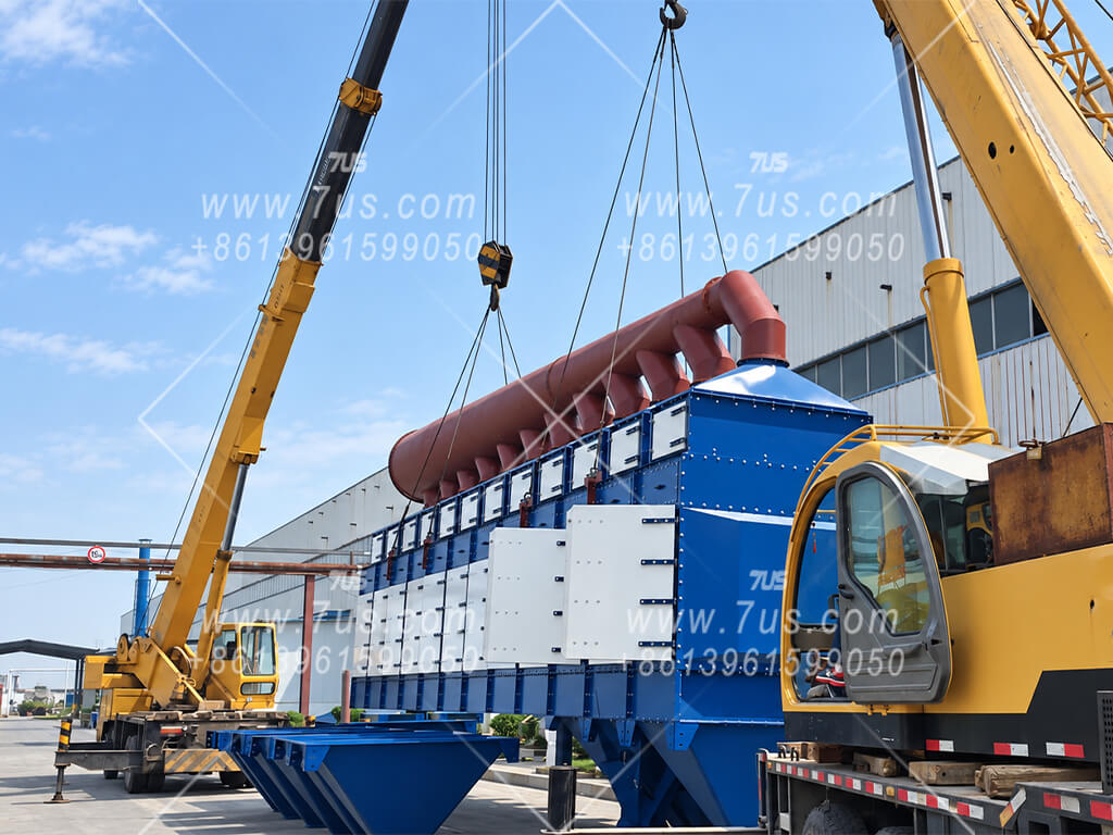
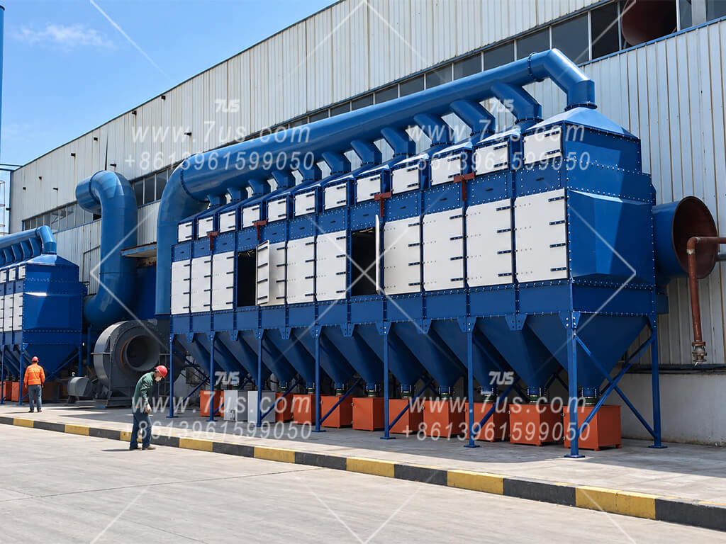
From Factory Trial Assembly to Site Installation

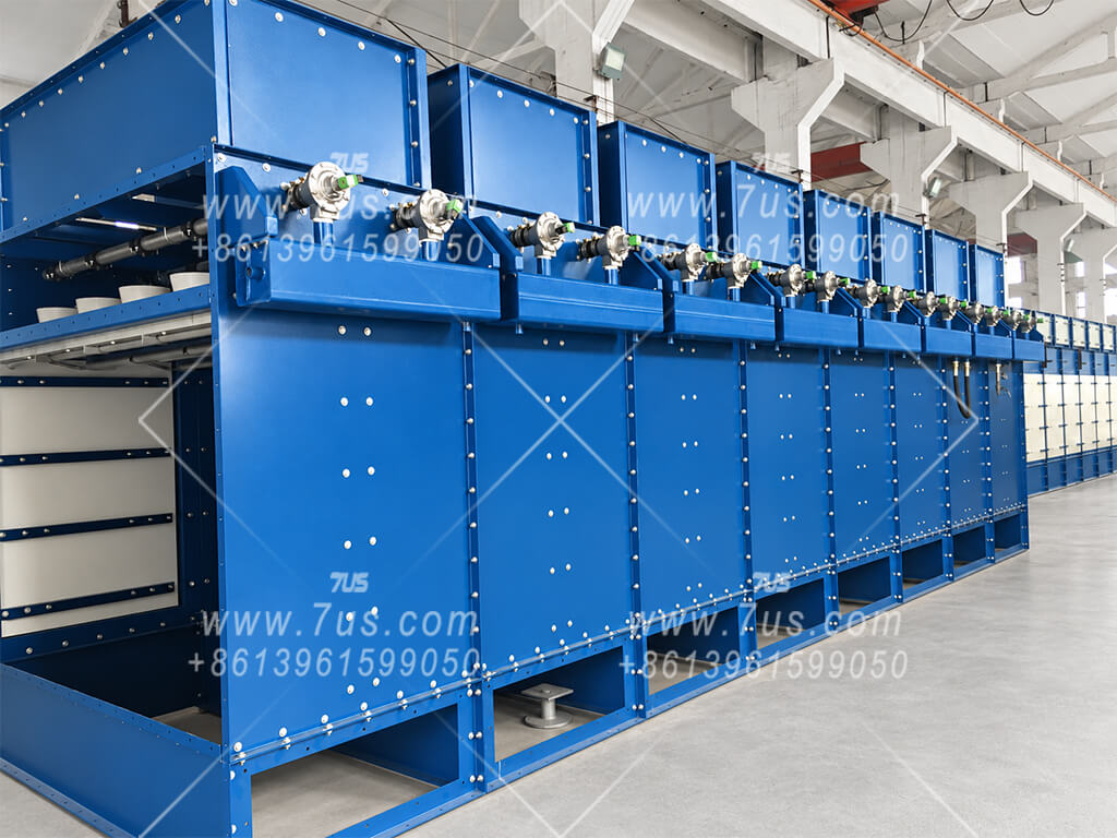
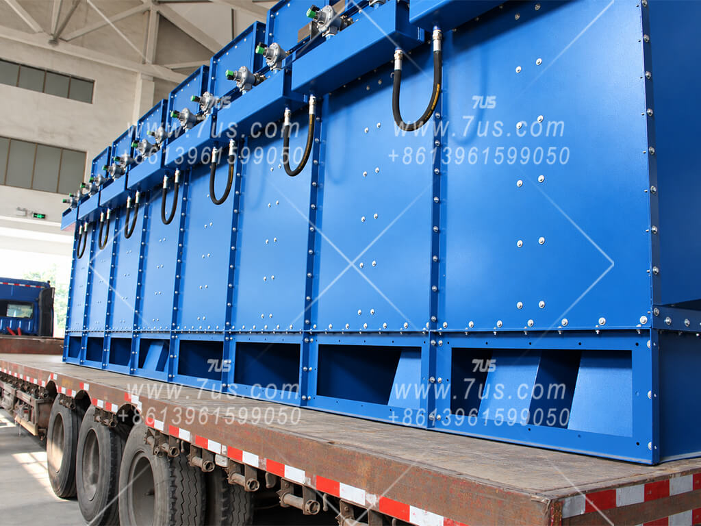
Large vertical collectors are prepared as transport-ready modular assemblies before dispatch. The final split between collector modules, hopper / support sections, fan packages and external ductwork is confirmed around transport, lifting access and the site installation plan.

Representative 7US vertical modular collector projects. The images show factory trial assembly, dispatch and field installation across different project configurations. Optional secondary final filtration is selected only where the emission target or return-air requirement calls for it.
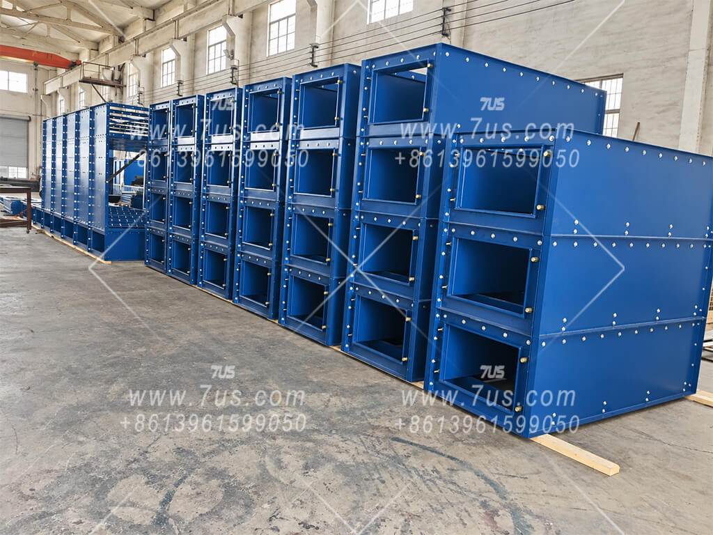
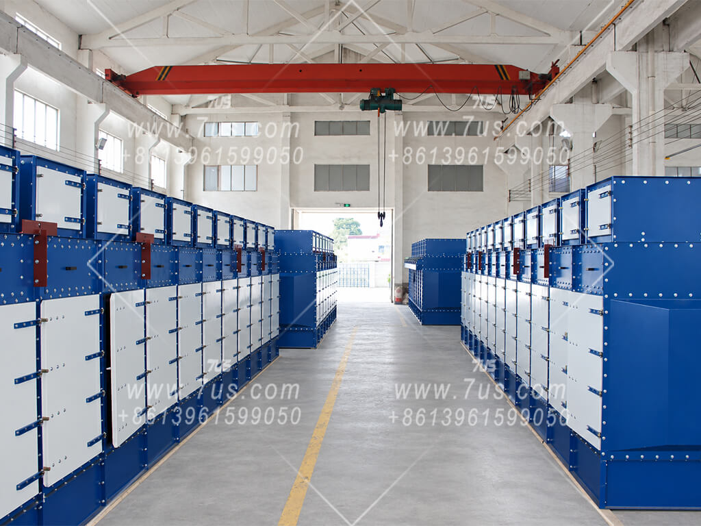
01 · FactoryTrial AssemblyModules are checked as complete collector assemblies before dispatch.
02 · DispatchPrepared for TransportEquipment is organized around the shipment and lifting plan.
03 · SiteInstallation & IntegrationCollectors are positioned, connected and completed with the project system.

Questions Buyers Usually Ask

The final DHC arrangement is confirmed around the dust conditions, required airflow, available installation space and system scope. These are the items most commonly discussed before quotation and drawing approval.

How is the DHC module arrangement selected?

First confirm the dust characteristics, filter media and design filtration velocity. The required effective filter area is then calculated from the airflow. Cartridge length, module depth and the number of side-by-side modules are selected around the available site space.

Can HEPA final filtration be integrated?

Yes. A secondary HEPA stage can be integrated when emission limits or return-air requirements call for it. The HEPA pressure drop is included when the fan and system pressure are selected.

Can the fan, control cabinet and safety components be included?

Yes. The collector body may be supplied separately, or as a package with fan, motor, electrical controls and selected safety components after airflow, system pressure, voltage and destination requirements are confirmed.

Can material, coating color and structural details be customized?

Yes. Q235 carbon steel, SS304 and SS316L are available. Coating color, plate thickness, reinforcement and selected structural details can be adapted for the project requirements.

Can you provide GA and DWG drawings?

Typical drawings can support initial selection. Detailed GA and DWG project drawings can be prepared after the final configuration, interfaces and order requirements are confirmed.

Preparing the public shell…