7US 7US Industrial dust collector since 1994
Custom industrial acid preparation

Sulfuric Acid
Dilution Systems

7US designs and manufactures custom sulfuric acid dilution systems for industrial acid and battery electrolyte preparation. Dilute concentrated sulfuric acid to the concentration or density your process requires, with coordinated mixing, monitoring and cooling. Batch size, tank arrangement and controls are tailored to your site.

Made to orderSingle or multiple recipesSemi-automatic or fully automatic
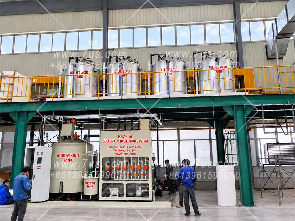
Sulfuric acid dilution installation with an acid mixing tank, valve control panel and elevated dilute acid storage tanks
A custom installation with acid mixing, valve control and dilute acid storage. Tank arrangement and equipment vary by project.

Designed for your process

Batch capacity, tank layout and acid specifications tailored to your requirements.

Your choice of control

Semi-automatic operation or fully automatic PLC/HMI control, configured for the project.

Concentration monitoring

Automatic systems use online density measurement with temperature compensation to display concentration.

Graphite heat exchange

Removes dilution heat while keeping acid and cooling water in separate flow paths.

01

How the Dilution System Works

Both semi-automatic and fully automatic systems follow the same dilution principle: start cooling-water circulation and confirm flow on the pipeline flowmeter, charge water, add higher-concentration sulfuric acid in stages, then verify the prepared batch. Measurement and pump-valve operation depend on the selected control option.

Cooling-water flow confirmed · water before acid
Sulfuric acid mixing and circulation cooling schematicCooling-water circulation is started first, and the operator confirms water flow on the pipeline flowmeter. Pure water is charged to the mixing tank before concentrated sulfuric acid is added in temperature-controlled stages. A circulation pump sends acid through a graphite heat exchanger and back to the tank through online density measurement on automatic systems. A separate customer cooling circuit supplies cold water and receives warmed water. Prepared acid is transferred to storage or the use point. Pure water Concentratedsulfuric acid Acid mixing tankBatch preparation Circulation pump Graphiteheat exchanger Onlinedensity*Acid return Customer coolingwater systemTower · reservoir · pumps Cold water supplyWarm water return To acid storage / use point *Fully automatic systemswith temperature compensation
Acid circuitCooling water circuit
Functional schematic only. Start cooling-water circulation and confirm flow on the pipeline flowmeter before filling. Acid is added in stages while cooling continues. The online density meter shown applies to fully automatic systems; semi-automatic systems use manual measurement. Layout and settings vary by project.
1

Start cooling water and confirm flow

Start cooling-water circulation before dilution begins. Check the pipeline flowmeter to confirm that cooling water is flowing through the heat exchanger. The circulation pump carries mixed acid through the graphite heat exchanger and back to the mixing tank. Acid and cooling water remain in separate paths and flow in opposite directions.

2

Charge water before adding acid

Introduce the specified pure water charge into the mixing tank first. The selected sequence may use the full calculated water quantity, or approximately 90% initially, with the remainder available for adjustment. Confirm the specified initial water charge is present before enabling acid feed. Only then add concentrated sulfuric acid slowly into the water. Never reverse this initial charging sequence.

3

Add acid in stages and remove heat

Dilution releases substantial heat, so acid is added in controlled stages while the mixture is circulated and cooled. In semi-automatic systems, operators respond to temperature alarms and control pumps and valves. Fully automatic systems use temperature interlocks to pause and resume acid addition.

4

Verify the batch and transfer

Check temperature, concentration or density, and final batch volume against the agreed requirements. Semi-automatic systems use manual sampling and measurement; fully automatic systems use online density measurement with temperature compensation. Transfer the qualified acid to its designated storage tank before preparing the next concentration.

Batch completion criteria

Specified temperature Specified concentration or density Batch volume within agreed tolerance

All three acceptance conditions must be satisfied. Final batch volume may differ from the target; the permitted deviation is defined in the project technical agreement.
Engineered for each project

Capacity, target specifications and operating sequence are tailored to the project. Each batch produces one concentration specification. Different concentrations can be prepared in successive batches, with transfer to the designated storage tank between batches.

Customer-supplied cooling circuit

Warmed cooling water returns to the customer's cooling tower and reservoir before recirculating. Where specified, cooling-water pH monitoring helps detect acid leakage and protect that system.

02

Fully Automatic or Semi-Automatic?

Both options use PLC controls and a touchscreen. The difference is how the batch is measured and operated: automatic feedback and pump-valve sequencing, or manual testing and operator-controlled steps.

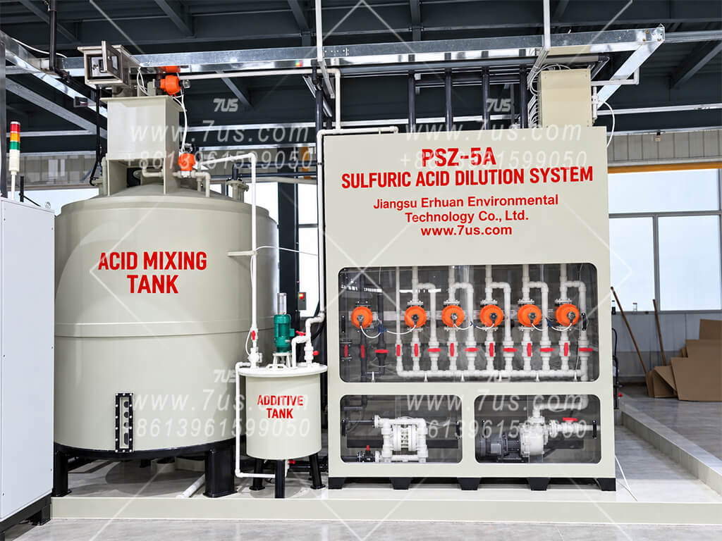
Fully automatic sulfuric acid dilution system with mixing tank, additive tank and pneumatic valve cabinet
Online feedback · Automatic operation

Fully Automatic System

Enter the target concentration or density, batch volume and temperature on the touchscreen, then start the programmed dilution sequence. PLC control operates pumps and valves using online measurements.

  • Online density measurement with temperature compensation and concentration conversion
  • Temperature and level alarms with automatic interlocks
  • Saved recipes and one-touch start for repeat batches
Prepare one concentration per batch. Transfer it to the designated storage tank before starting the next recipe.
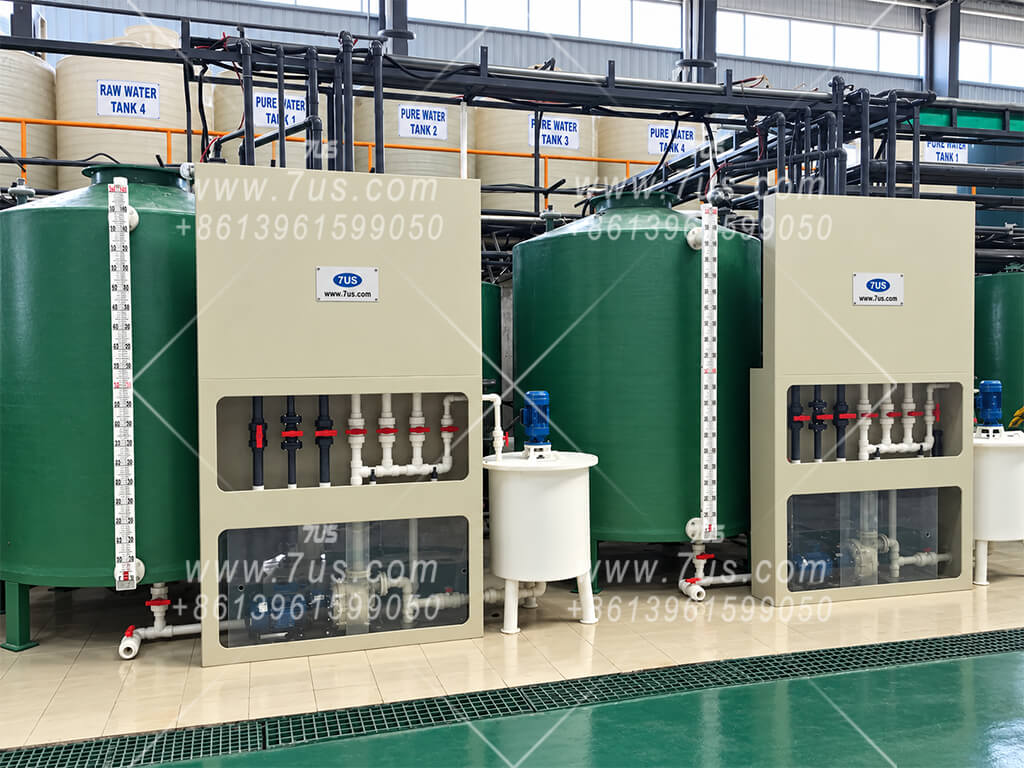
Semi-automatic sulfuric acid dilution installation with green mixing tanks, manual valve cabinets and level indicators
Manual testing · Operator-controlled steps

Semi-Automatic System

Operators calculate the required water and acid quantities using sulfuric acid concentration–density–temperature reference data. They operate pumps and valves and check the batch by manual sampling.

  • Manual concentration or density measurement
  • Temperature and level alarms prompt operator action
  • Operator-managed staged acid addition and finished-acid transfer
Operators confirm the specified temperature, concentration or density, and agreed volume tolerance before transferring the batch.
Control options at a glance
FunctionFully automaticSemi-automatic
PLC & touchscreenIncludedIncluded
Batch setupEnter target concentration or density, volume and temperatureCalculate feed quantities using reference data
Concentration / density checkOnline density meter with temperature compensationManual sampling and measurement
Pump & valve operationAutomatic PLC sequencingOperator-controlled
Temperature & level protectionAlarms plus automatic interlocksAlarms; operator intervention
Repeated batchesSaved recipes with one-touch startManual execution of each batch
Batch completion confirmationSystem checks against configured acceptance conditionsOperator checks against agreed requirements
Remote / MES integrationAvailable, configured for the projectNot included in this control option

Two control options, each engineered to order. The photographs show individual installations, not fixed standard models. Capacity, tank arrangement, instruments and accessories are selected for each project.

03

Fully Automatic Sulfuric Acid Dilution System

Set the batch requirements, start the sequence and let online feedback guide acid preparation. The PLC coordinates pumps, valves and temperature interlocks.

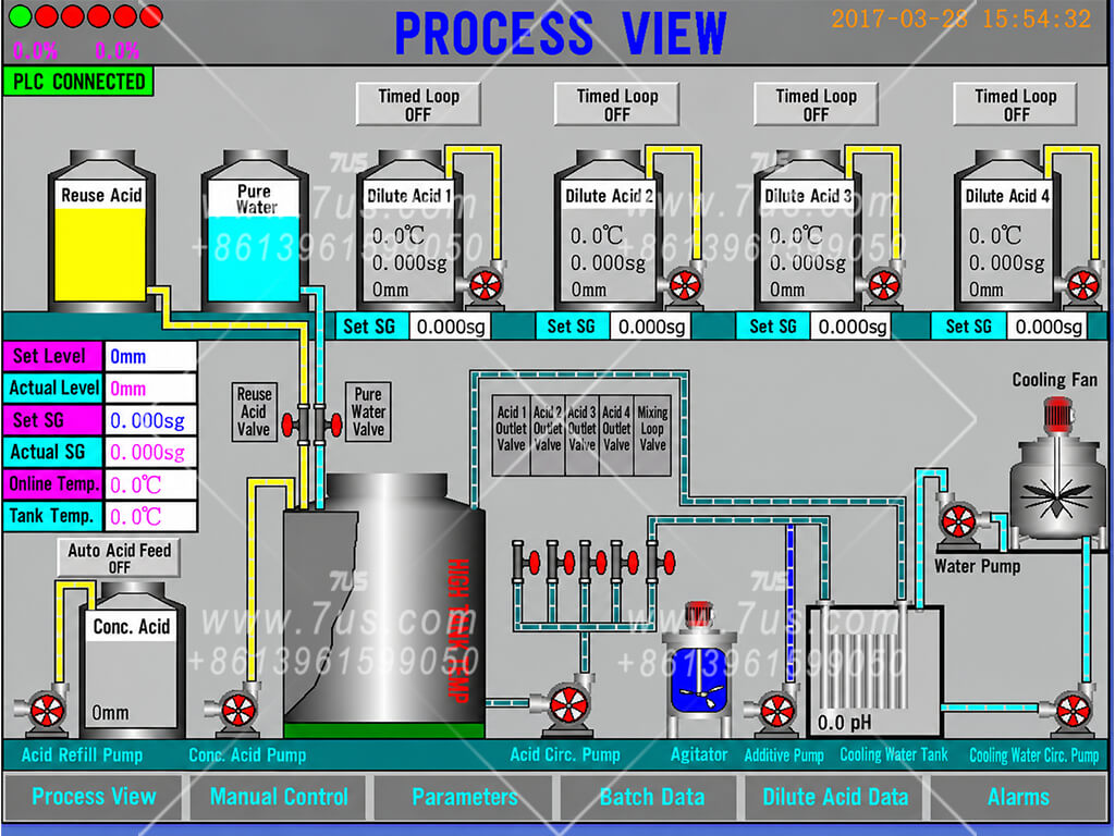
English HMI process view showing acid and water feeds, mixing, four dilute acid storage tanks, pumps, valves and cooling water circulation
Example HMI process view. Tank count, optional functions and screen layout are configured for each project.
Recipe setup & repeat operation

Three parameters. One batch at a time.

For the first recipe setup, enter the target concentration or density, batch volume and temperature on the touchscreen. Start the programmed dilution sequence after completing the required operating preparations.

Frequently used recipes can be saved as shortcut buttons on the HMI home screen for one-touch start on later runs.

Complete one concentration per batch, transfer the qualified acid to its designated storage tank, then start the next recipe.
01 · Actual solution measurement

Online density feedback

The density meter has a measurement accuracy of ±0.002 g/cm³, with built-in temperature compensation to convert density into the corresponding sulfuric acid concentration.

Actual solution readings account for residual acid in tanks and piping. If density remains above target, the programmed sequence may add controlled quantities of pure water to the already diluted, circulating and cooled mixture. This adjustment follows the approved process limits; water must never be charged onto concentrated sulfuric acid.

02 · Temperature-linked acid feed

Stop, cool and resume

Start cooling-water circulation and confirm water flow on the pipeline flowmeter before charging the specified initial water quantity. Concentrated acid feed begins only after that water charge is confirmed. Online temperature monitoring stops concentrated acid addition when mixed-acid temperature exceeds 60°C; cooling continues and acid addition resumes below 45°C.

The cycle repeats as needed to protect the plastic piping, valves and mixing tank. These feed-control thresholds are separate from the final product temperature requirement.

03 · Small additions near the target

Intermittent diaphragm-pump dosing

An air-operated diaphragm pump supplies concentrated sulfuric acid. Solenoid valves control the timing and frequency of its compressed-air drive.

Near the target, brief, intermittent operation reduces each acid addition for finer adjustment with online density feedback. The selected pump permits dry running within its operating specifications.

04 · Sensor calibration & cleaning

Maintain dependable readings

The acid-contact sensing element is a glass ball selected for this sulfuric acid service. Automatic pure-water rinsing helps remove deposits that could affect measurement.

The meter can be calibrated against a laboratory-prepared dilute sulfuric acid reference solution with verified density. The stated accuracy is the instrument's density measurement specification.

Batch acceptance and volume tolerance

Completion requires the specified temperature and concentration or density, plus a final volume within the agreed tolerance. Residual liquid in tanks and piping can cause volume variation. This system uses online feedback rather than weighing each feed quantity; permitted deviation is defined in the project technical agreement.

04

Semi-Automatic Sulfuric Acid Dilution System

A PLC and touchscreen support operation, while the operator controls dosing, checks samples and confirms each completed batch.

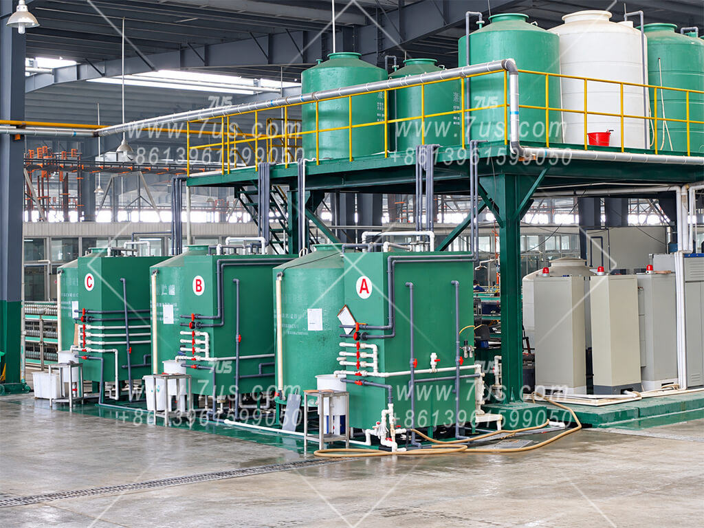
Semi-automatic sulfuric acid dilution installation with green mixing tanks, control cabinets and manually operated valves
Semi-automatic installation example. Tank arrangement and equipment layout are tailored to the customer's site.
Operator-led batch preparation

Prepare, dose, check and transfer.

  1. Prepare the batch. Calculate water and acid quantities for the required concentration or density and volume, using concentration–density–temperature reference data.
  2. Start cooling water. Confirm flow. Water before acid. Start cooling-water circulation and check the pipeline flowmeter to confirm water flow through the heat exchanger. Charge the specified pure-water quantity into the mixing tank and confirm it is present before starting any concentrated-acid feed. Only then add concentrated sulfuric acid slowly, in controlled stages, into the water.
  3. Control addition and check samples. Operate pumps and valves, respond to temperature and level alarms, and adjust the batch according to measured results.
  4. Confirm and transfer. Verify the required temperature and concentration or density, plus volume within the agreed tolerance, before transferring to storage.
01 · Feed calculation

Calculated quantities guide the batch

The operator determines the initial water and acid charges from the feed-acid specification and target requirements. Residual solution in tanks and piping must be considered when preparing the next batch.

The calculated charge is followed by sample checks and adjustment to confirm the actual solution meets the target.

02 · Manual quality checks

Sample, measure and adjust

Concentration or density is checked by manual sampling. Density results are interpreted at the applicable reference temperature, using suitable temperature correction where needed.

Any final water adjustment is limited to the already diluted, circulating and cooled mixture, under the approved operating procedure. Never add water to concentrated sulfuric acid. Recheck the mixed solution before confirming acceptance.

03 · Alarms & operator response

Supervise temperature and level

Temperature and liquid-level alarms prompt the operator to take action. The operator controls acid-feed pumps and valves and pauses addition when the temperature limit is reached.

Keep cooling in operation and resume acid addition only when the specified restart conditions are met. Alarm limits and operating procedures are defined for each project.

04 · Batch release

Confirm one concentration at a time

The operator confirms the batch against the agreed acceptance requirements, then operates the transfer to its designated dilute-acid storage tank.

Prepare the next concentration after transfer. Residual liquid and non-weighing feed can cause volume variation, so the permissible deviation is specified in the technical agreement.

Plan for operator supervision

This control option requires operator attendance for dosing, alarm response, sample testing and batch release. Select the configuration according to the site's staffing, testing facilities, batch frequency and process requirements.

05

Construction & Protection

Storage-tank materials, heat-exchanger options and mixing-tank protection. Equipment sizes, materials and arrangements are tailored to each project.

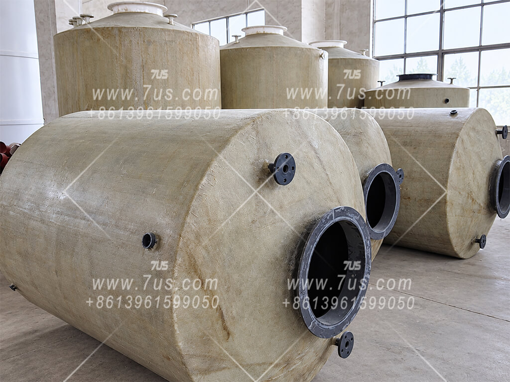
Concentrated-acid tank · PVC / FRP

Concentrated-acid tank · PVC / FRP

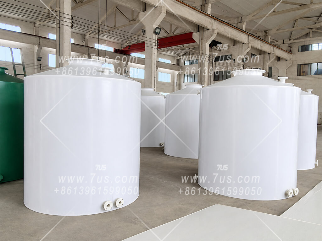
A PVC tank forms the acid-contact layer, with external wound glass-fibre reinforcement (FRP) for structural strength. This is the concentrated-acid tank supplied within the dilution system; a separate bulk acid-storage installation is agreed at the project boundary.

Dilute-acid tank · Welded PP

Dilute-acid tank · Welded PP

Manufactured from welded polypropylene (PP) sheet for prepared dilute sulfuric acid. Capacity, connections and the number of storage tanks are selected for the required batch volumes and acid recipes.

Dilute-acid tank · Thick-wall PE

Dilute-acid tank · Thick-wall PE

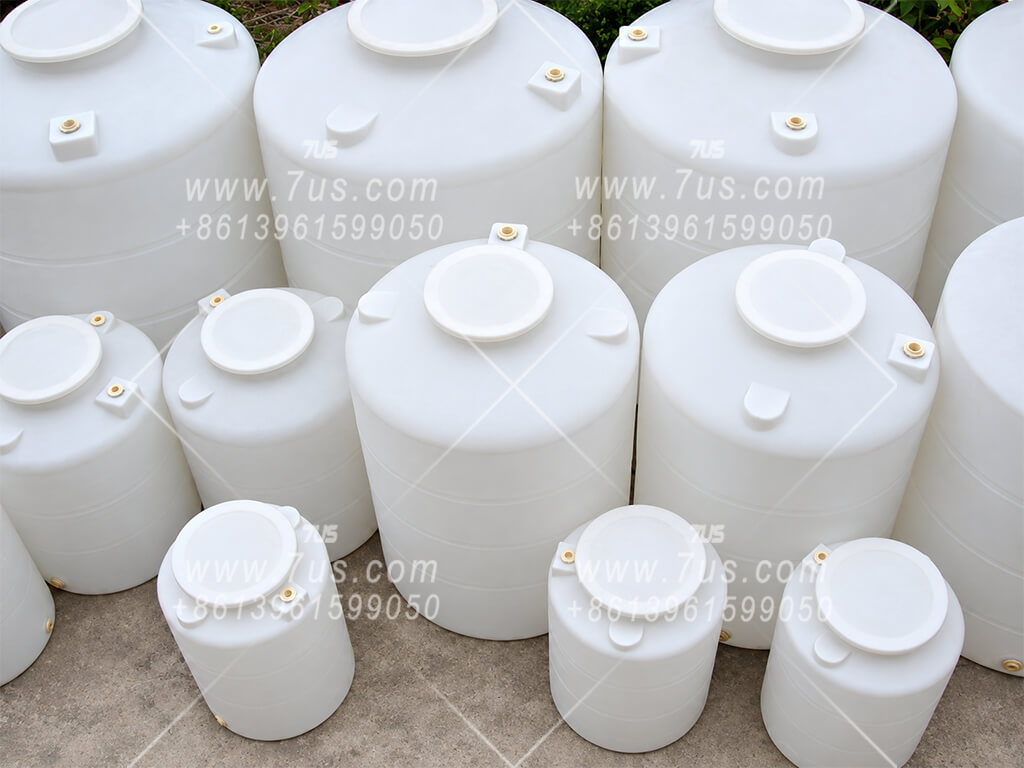
A thick-wall polyethylene (PE) tank manufactured by rotational moulding is another storage option. Material suitability and wall thickness are selected for the actual acid concentration, temperature and installation conditions.

Shell-and-tube graphite heat exchanger

Shell-and-tube graphite heat exchanger

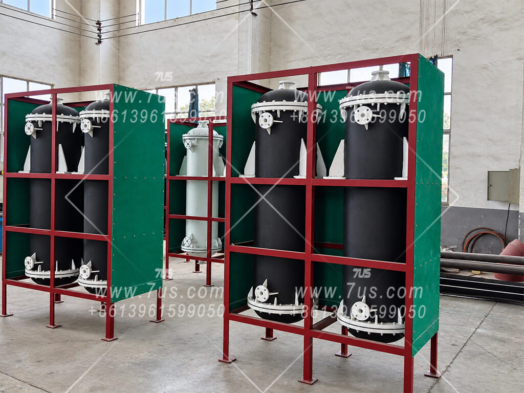
The usual heat-exchanger configuration uses graphite tubes and a plastic outer shell. Acid flows inside the tubes and cooling water flows outside, in counterflow. The two liquids remain in separate circuits during normal operation.

Alloy-coil heat exchanger

Alloy-coil heat exchanger

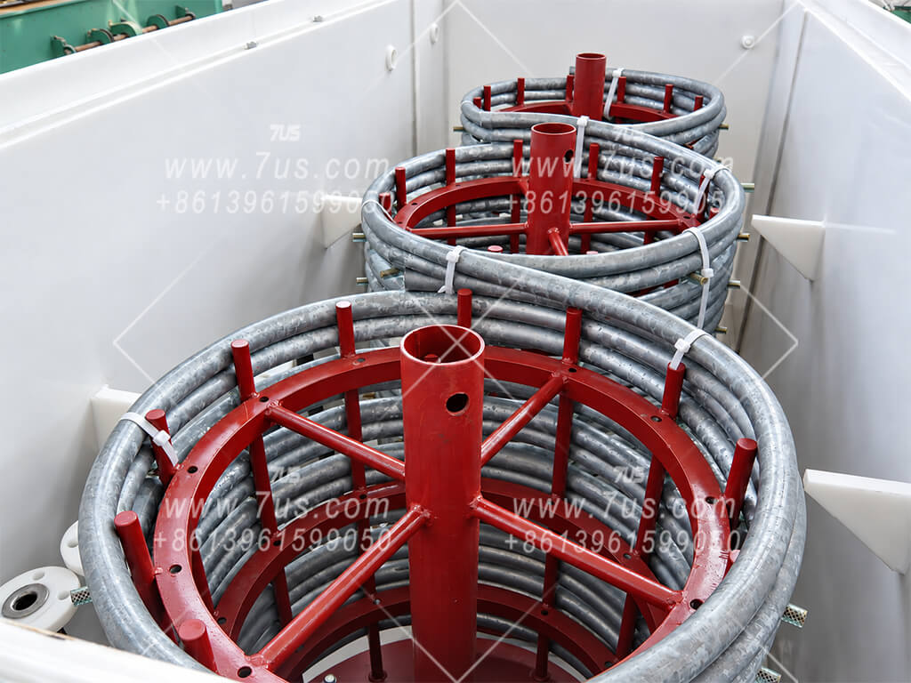
An alternative coil-type exchanger can be considered where appropriate. The Hastelloy option is limited to sulfuric acid concentrations below 40% in this system, with the alloy grade, temperature and actual solution composition reviewed for each project.

Concentrated-acid withdrawal & materials

Top withdrawal & material selection

Acid is drawn through the tank top, avoiding bottom outlet penetrations. An air-operated diaphragm pump is selected with dry-running capability within its manufacturer's operating limits.

Where the piping and valve arrangement permits, acid in the vertical suction line can drain back into the tank after shutdown.

Typical acid-contact materials

Concentrated-acid tank
PVC + external wound FRP
Dilute-acid tank
Welded PP or thick-wall moulded PE
Concentrated-acid piping
Thick-wall chemical-service UPVC
Other acid piping
PP
Concentrated-acid valves
PTFE acid-contact components
Other acid valves
PP; optional PTFE

Materials are confirmed for the specified acid concentration, temperature, pressure and solution composition. Mixing-tank options are described below.

01 · Mixing tank option A

PP / FRP composite tank

A polypropylene (PP) tank forms the acid-contact barrier, with wound glass-fibre reinforcement on the outside. The PP layer provides corrosion resistance while the external FRP layer reinforces the tank structure.

The tank is designed for the specified acid concentration, operating temperature, liquid head and installation conditions.

Material arrangement: acid-contact PP tank + external wound FRP reinforcement.
02 · Mixing tank option B

Double-wall PP tank

A PP inner tank is fitted inside a separate PP outer tank, leaving an inspection space between the two walls. A transparent sight glass provides a visible check for liquid accumulating in this space.

Operators inspect the sight glass for signs of leakage. Tank dimensions and the inspection arrangement are configured for the project.

Material arrangement: PP inner tank + inspection space + PP outer tank, with a visual leakage check.
03 · Separate heat-transfer paths

Graphite heat exchanger

The usual configuration uses a graphite heat exchanger with a plastic outer shell. Acid flows inside the graphite tubes, while cooling water flows outside them, in the opposite direction, to support heat transfer.

The tube wall separates the acid and cooling-water circuits during normal operation. Heat is removed without mixing the two liquids.

Alternative: a Hastelloy heat exchanger can be considered for this system at sulfuric acid concentrations below 40%, subject to review of temperature and the actual solution composition.
04 · Customer cooling-water system

Cooling circulation & pH checks

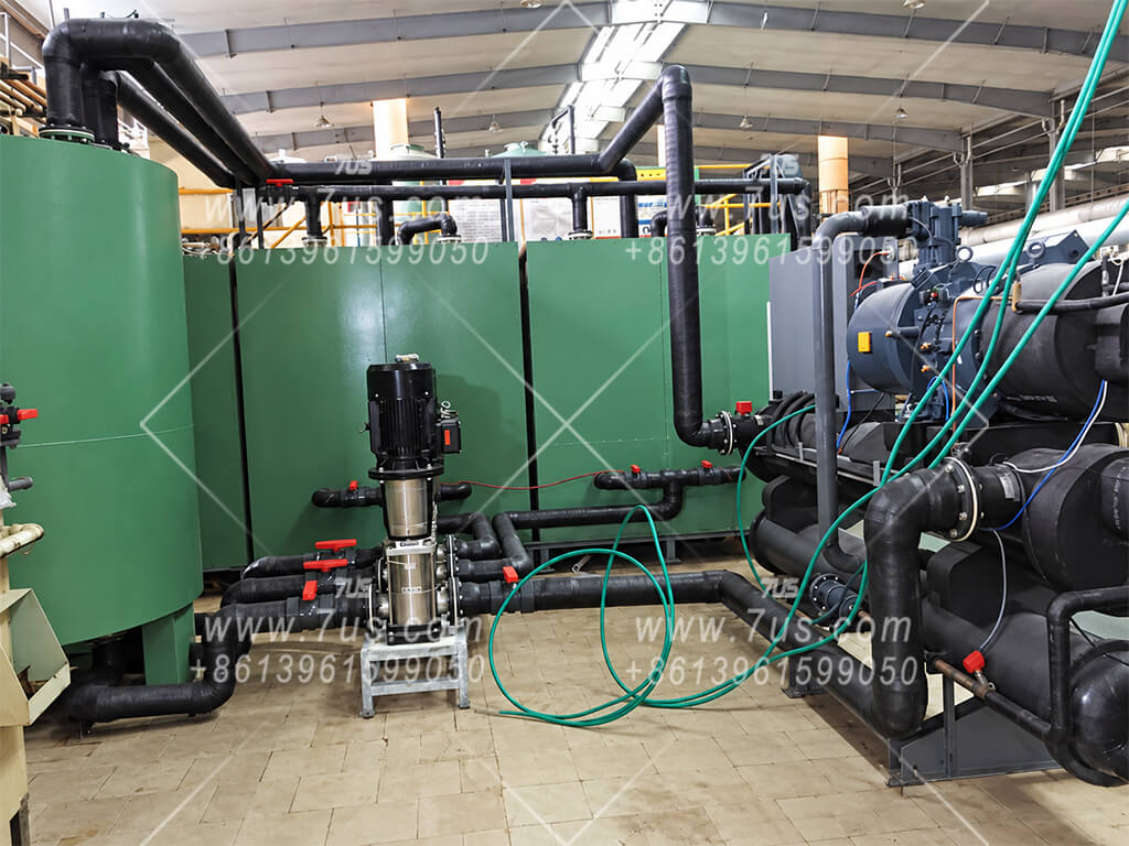
The customer supplies the cooling tower, cooling-water reservoir and circulation system. Warm water leaving the heat exchanger returns to this system for cooling before being supplied to the machine again.

Cooling-water pH monitoring, where specified, helps identify acid leakage into the cooling circuit and protect the customer's cooling equipment.

Startup check: start cooling-water circulation and confirm flow on the pipeline flowmeter before charging the mixing tank.
05 · Tank breathing & pressure balance

Tank breathing vent with mist capture

A small top-mounted breathing vent, typically DN100, allows gas to enter or leave as liquid level and temperature change, helping balance pressure between the tank interior and the surrounding atmosphere.

An acid-mist collector on the vent uses PP mesh and hollow polyhedral packing to capture entrained acid droplets. These droplets coalesce and drain back into the tank. The breathing vent and collector require regular inspection and maintenance.

Separate functions: the breathing vent balances tank pressure; dilution heat is removed primarily by the heat exchanger and circulating cooling water.
06 · Maintenance access

Covered inspection opening

A top inspection opening provides access for maintenance and remains covered during operation. Access arrangements are selected to suit the tank and installation.

Maintenance requires shutdown and isolation of the equipment. Any entry into the tank must follow the site's confined-space entry procedure.

Plastic process components: mixing tanks, piping and valves are selected for sulfuric acid service within the agreed concentration and temperature limits.
Protection works together with the correct charging sequence

Confirm cooling-water flow, charge the specified initial water quantity, then add concentrated sulfuric acid slowly in controlled stages. Tank reinforcement, cooling, venting and alarms support operation; they do not replace water-first charging or the approved operating procedure.

06

Optional Diluent & Formulation Dosing

Project-specific options for a suitable lower-concentration acid feed and formulation additives.

Welded PP formulation-additive mixing tanks with top-mounted agitators

PP additive mixing tanks

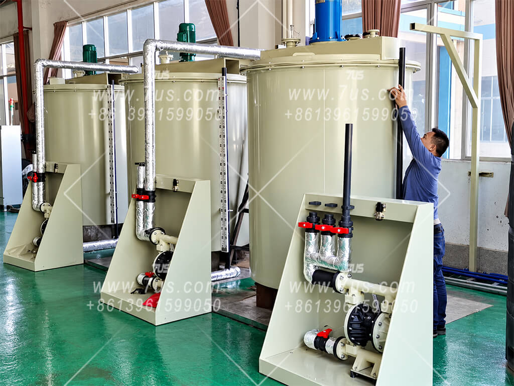
Welded PP tanks with agitators can be configured for preparing suitable formulation additives. Tank capacity, mixing equipment and the dosing connection are selected for the customer's formulation.

01 · Addition timing

Dose at the appropriate stage

Compatible additives that do not affect acid concentration or density measurement may be added during mixing. If they affect the measurement or target formulation, dose them into the transfer line after the acid batch is accepted.

02 · Mixing options

Agitator or circulation loop

For larger additive quantities, use a storage-tank agitator or a loop drawing liquid from the tank bottom and returning it near the top. Air-bubble mixing is an option only where suitable, using clean, oil-free air and appropriate mist control.

03 · Optional diluent

Lower-concentration acid feed

A suitable lower-concentration acid may replace some or all of the pure-water diluent. The target concentration lies between the two feeds. The stronger feed need not be 98% acid; it only needs to exceed the target. Reused acid requires impurity and compatibility assessment.

04 · Separate feed tanks

Independent storage & connections

Keep the lower-concentration acid tank separate from the pure-water tank, each with its own valved line to the mixing tank. Establish the approved diluent charge first, then add the higher-concentration acid in controlled stages with cooling and temperature controls.

Configured for the actual process

These are optional functions. Feed composition, additive compatibility, dosing timing and the final acceptance criteria are agreed for each project.

07

Application Cases

Real installations show how acid preparation and supply systems are adapted to different production sites.

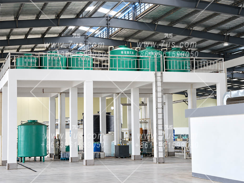
6 m-high central acid preparation and supply station
Installation example

6 m-high central acid preparation station

An elevated central station uses the available height difference for gravity-fed acid delivery, reducing reliance on transfer pumps and associated pump and valve wear.

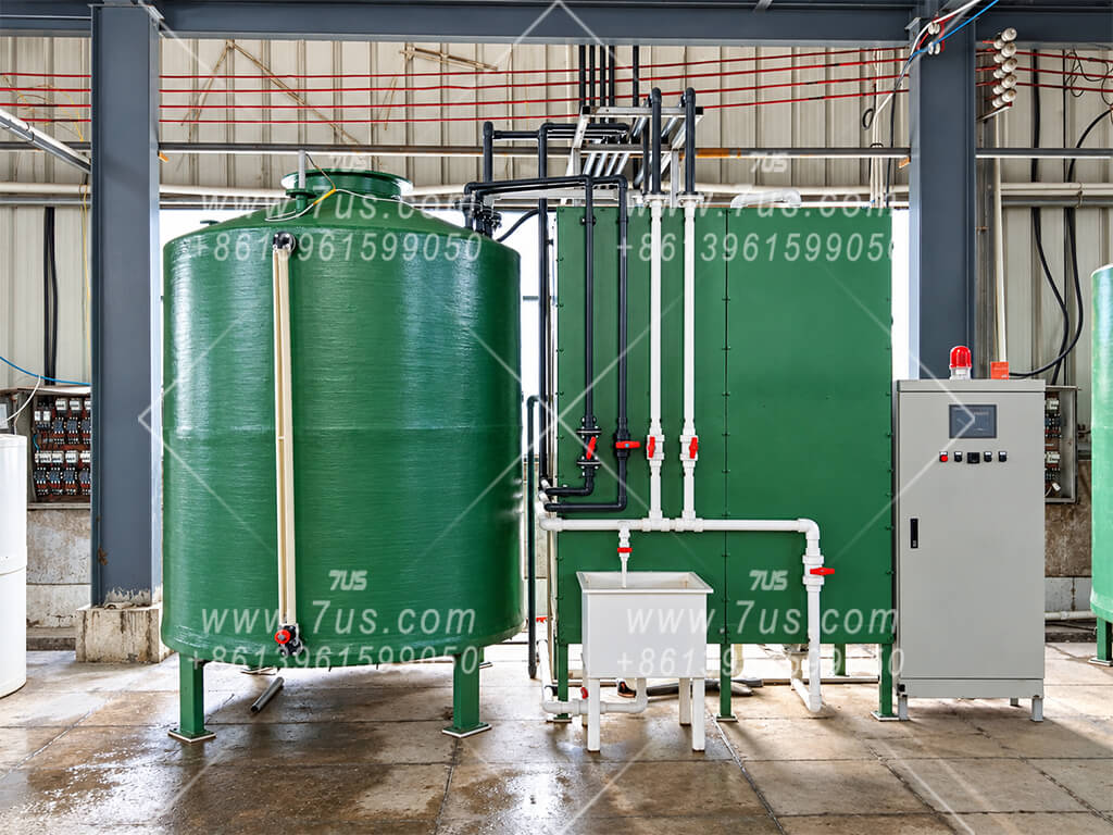
Sulfuric acid mixing tank and heat exchanger installation
Installation example

Mixing tank & heat exchanger

The core dilution equipment combines an acid mixing tank with a heat exchanger to remove the heat released during dilution. Tank capacity and heat-exchange duty are matched to the required batch.

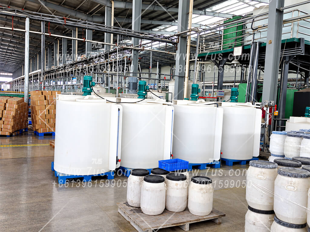
Central sulfuric acid electrolyte preparation and supply installation for electric-bicycle and electric-moped lead-acid batteries
Installation example

E-bike & electric-moped electrolyte centre

A central sulfuric acid electrolyte preparation and supply installation for lead-acid batteries used in electric bicycles and electric mopeds. Prepared electrolyte is distributed to the required production points.

Acid preparation installation at a lithium-battery materials plant
Installation example

Lithium-battery materials plant

An acid preparation installation serving a lithium-battery materials plant. Target concentration or density, batch volume and delivery arrangement are configured for the plant’s process.

Sulfuric acid supply system for lead-acid battery paste mixing
Installation example

Acid supply for battery paste mixing

An acid supply system serving the paste-mixing stage of lead-acid battery production, preparing and delivering dilute sulfuric acid for the production formulation.

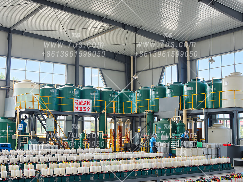
Central acid supply station with three sulfuric acid dilution systems
Installation example

Central station with three dilution systems

Three acid preparation systems form a central supply station. Their arrangement, storage capacities and supply connections are tailored to the production site.

Each installation is custom-designed. The photos illustrate project layouts; tank capacities, control functions, materials and supply scope are agreed individually.

08

Industry Applications

Configure the acid preparation system around the process, rather than a single standard machine specification.

Lead-acid batteries

Electrolyte preparation and acid supply for paste mixing in lead-acid battery production. Concentration or density, batch volume and temperature targets are configured for the production process.

Lithium-battery materials

Dilute sulfuric acid preparation for lithium-battery material manufacturing. Acid recipes, storage capacities and supply connections are matched to the plant’s process requirements.

Mineral extraction

Process-acid preparation for manganese and other suitable mineral-extraction applications. Feed composition, required acid strength and delivery capacity are reviewed for the extraction process.

Metal surface treatment

Preparation of sulfuric acid solutions for compatible pickling, descaling and metal surface-treatment processes. The dilution system prepares the acid; downstream bath operation is defined separately.

Water & wastewater

Dilute acid reagent preparation for pH adjustment, neutralisation and suitable ion-exchange resin regeneration processes. Reagent dosing and regeneration equipment are specified separately.

Electronics & PCB

Acid preparation for printed-circuit-board and other suitable electronics processes. Feed purity, contamination control and acid-contact materials are specified for the required chemical grade.

Chemical formulations

Process-acid preparation for suitable pesticide, pigment and specialty-chemical formulations, with optional additive dosing. Biopharmaceutical applications require a separate review of purity, cleaning and validation needs.

Fertiliser & agriculture

Process-acid preparation for fertiliser production where diluted sulfuric acid is required. Controlled seed-treatment applications, including cottonseed projects, are configured for the approved crop-specific process.

Application suitability is assessed for each project. Specify the feed acid, target concentration or density, batch volume, delivery temperature and purity requirements. Semiconductor-grade or validated pharmaceutical service requires a dedicated design review; it is not a standard specification.

09

Capacity & System Sizing

Balance batch output, cooling performance, available floor space and equipment investment.

Typical batch configuration

4 m³ per batch · 5 m³ tanks

A common configuration uses nominal 5 m³ mixing and dilute-acid storage tanks, with a normal target batch volume of 4 m³. For target sulfuric acid concentrations below 50%, configurations can be selected for a batch dilution time of up to 4 hours or up to 2 hours under the agreed design conditions.

4 m³ / ≤ 4 hTypical batch-time option
4 m³ / ≤ 2 hHigher-throughput option

Batch time is confirmed for the specified feed acid, cooling-water inlet temperature and flow, and final acid temperature.

Cooling & production rate

Heat removal sets the pace

With other conditions unchanged and adequate cooling-water supply, a larger effective heat-transfer area and colder incoming cooling water generally shorten cooling time. Actual output also depends on cooling-water flow, acid circulation and the target product temperature.

Ambient conditions mainly influence output through the customer's cooling-water system. Cooler weather may improve cooling-tower performance; ambient temperature alone does not determine batch capacity.

Heat-exchanger duty and customer-supplied cooling-water conditions are matched during project design.

Expansion & custom design

Multiple systems or a faster batch

Higher production demand can be served by two, three or more dilution systems, with coordinated storage and acid distribution. The customer's cooling-water system must support the combined heat load.

A requirement to prepare 4 m³ in 1 hour or less calls for a custom design. Heat-exchange duty, feed and circulation capacity, footprint and investment are assessed together for the required production schedule.

Select the number of systems and batch-time target around actual daily demand and operating hours.

Working volume & overflow routing

Reserved space above the normal batch

Using a 5 m³ tank for a normal 4 m³ batch leaves approximately 1 m³ of nominal capacity as reserve space. This provides additional margin for abnormal liquid-level conditions; it does not guarantee that overfilling cannot occur.

Top overflow connections route excess liquid through acid-resistant piping to a designated corrosion-resistant collection channel connected to the site's wastewater treatment system. The collection and treatment arrangements are agreed at the project boundary.

Normal operating levels and overflow connections are defined for the actual tank design.

Batch time and continuous supply are assessed separately. Filling, product transfer and batch changeover are included when calculating the overall production cycle and supply capacity.

10

Site & Installation Requirements

Prepare the indoor work area and utilities before equipment installation.

Installation environment

Indoor location & winter protection

Install the system indoors, protected from rain, direct sunlight and weather exposure that can accelerate plastic ageing. Provide ventilation suitable for the process and local requirements.

For cold climates, assess insulation or heating against the freezing characteristics of the actual acid concentrations and the operating conditions.

Foundation & controlled drainage

Acid-resistant floor & collection

Provide a load-bearing foundation with an acid-resistant surface, such as a suitably specified resin-and-glass-fibre lining or acid-resistant tiles. Materials are selected for the acid exposure and expected loads.

Use corrosion-resistant collection channels and grating covers. Route overflow and approved cleaning effluent to designated containment and wastewater treatment; keep it separate from stormwater and uncontrolled drains.

Customer utilities

Cooling water, water, power & air

The customer provides the external cooling-water system, including the cooling tower or other cooling source, reservoir and circulation facilities. Inlet temperature, flow, pressure and water quality are confirmed during design.

Provide dilution water of the specified purity, a suitable electrical supply and compressed air for the selected pumps and valves. Utility consumption and connection points are stated in the project documents.

Access & emergency facilities

Controlled work area & clear escape routes

Reserve operating and maintenance space, keep emergency routes clear and restrict access to trained, authorised personnel. Barriers, a dedicated operating room or monitoring may be specified according to the site assessment.

The owner provides accessible emergency eyewash and shower facilities, suitable PPE and a compatible spill-response kit with trained responders, selected under the acid SDS, site risk assessment and applicable local requirements.

These site-preparation items are planning guidance. Civil works, external utilities and emergency facilities are owner responsibilities unless included explicitly in the agreed scope.

11

Supply Boundary & Project Requirements

Define the equipment interfaces and project responsibilities before finalising the configuration.

Configurable equipment supply

From feed tanks to prepared-acid storage

The configurable equipment boundary extends from the system’s dilution-water and concentrated-acid feed tanks to the dilute-acid storage tanks. Mixing equipment, heat exchangers, pumps, valves, instrumentation, controls and internal piping can be included as agreed.

Tank quantities, capacities, materials, automation and optional formulation functions are defined in the quotation and technical agreement.

Owner-supplied external facilities

Bulk acid storage & site infrastructure

Separate large-capacity concentrated-acid storage is normally supplied by the owner. External transfer piping, cooling-water facilities, civil works, drainage, wastewater treatment and emergency facilities are outside the standard equipment scope unless expressly agreed.

Steel with PTFE lining may be considered for external bulk-acid tanks and transfer piping. Any alternative, including thick-wall UPVC for a short connection, requires the owner’s site-specific compatibility and safety assessment.

Project preparation

Confirm the process & operating conditions

Provide feed-acid composition, target concentration or density, batch volume, required temperature, daily demand and operating hours. Also specify available cooling water, utilities, indoor space and any purity or additive requirements.

These inputs determine batch time, tank arrangement, heat-exchanger duty, materials and the number of dilution systems. Final supply and acceptance criteria follow the agreed project documents.

Purchasing & site responsibilities

Qualified industrial end users

For this product, 7US supplies qualified direct industrial end users. Supply to private individuals, intermediaries or system integrators, and disclosure of detailed proprietary engineering information to them, are outside this product’s sales policy.

The purchaser is responsible for applicable chemical-purchase and storage permissions, required registrations, operating records and local site approvals. Requirements vary by location; relevant qualifications are confirmed before supply.

The quotation, technical agreement and approved project drawings define the final supply boundary. Proprietary design information is shared with the qualified end user as needed for the agreed project.

12

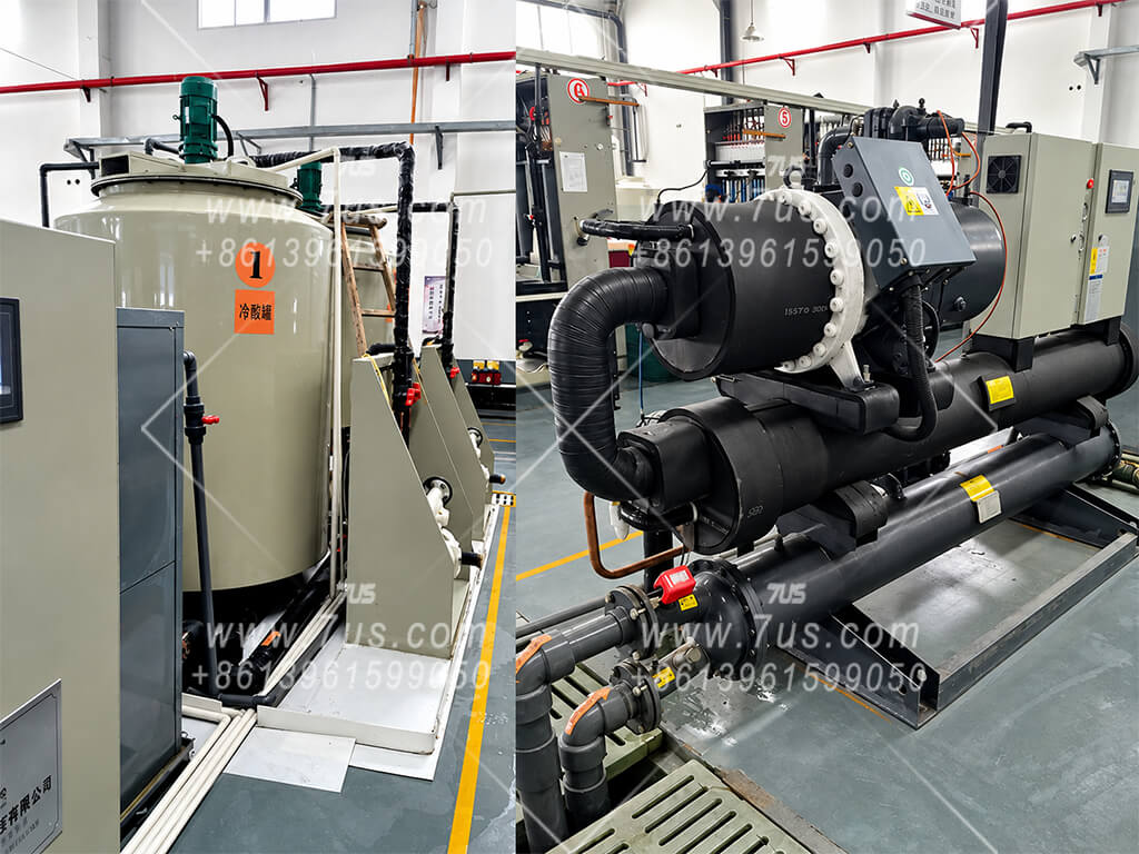
Sulfuric Acid & Gel Electrolyte Cooling

Separate downstream cooling systems bring prepared electrolyte to the temperature required by the battery production process. Select the cooling arrangement to suit the formulation and production schedule.

Ordinary sulfuric acid electrolyte

Alternating A/B acid cooling & supply

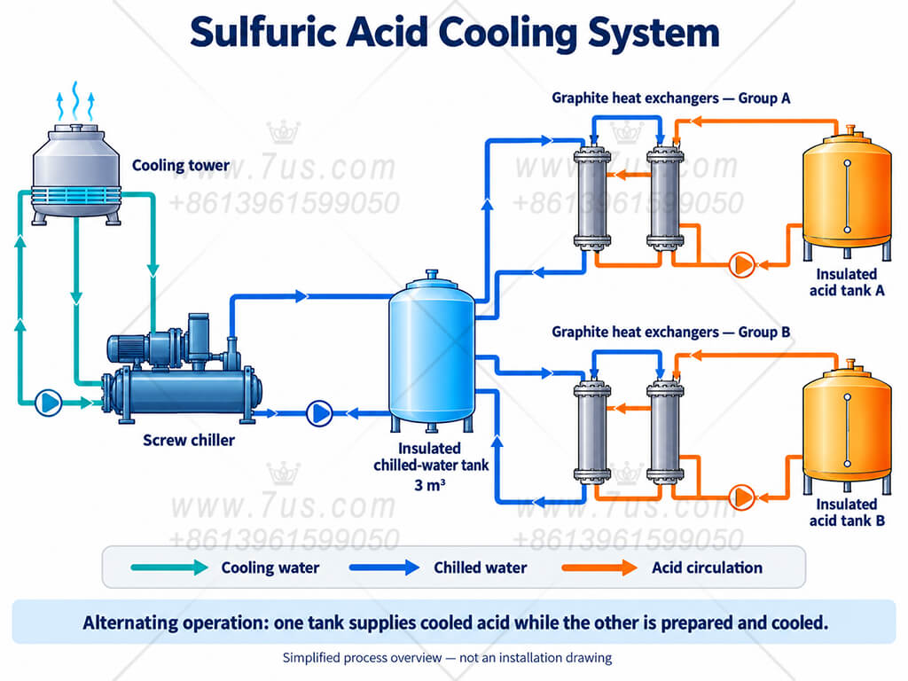
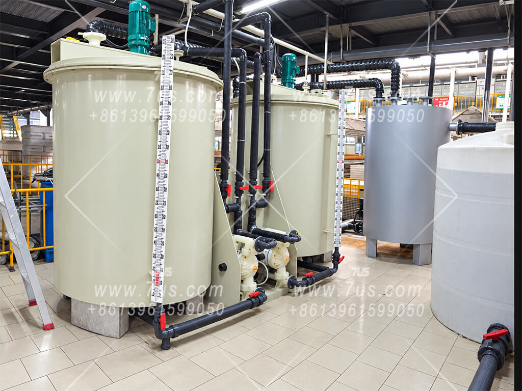
Two graphite heat-exchanger groups and two insulated acid tanks support alternating operation. One tank supplies cooled acid to production while the other tank is prepared and cooled for the next supply cycle.

  1. Tank A supplies acid. Tank B is prepared and cooled through its graphite heat-exchanger group.
  2. Confirm Tank B is ready. When Tank A is depleted and Tank B has reached the required temperature, switch the supply to Tank B.
  3. Prepare Tank A. Refill and cool Tank A while Tank B supplies production; repeat the alternating cycle.

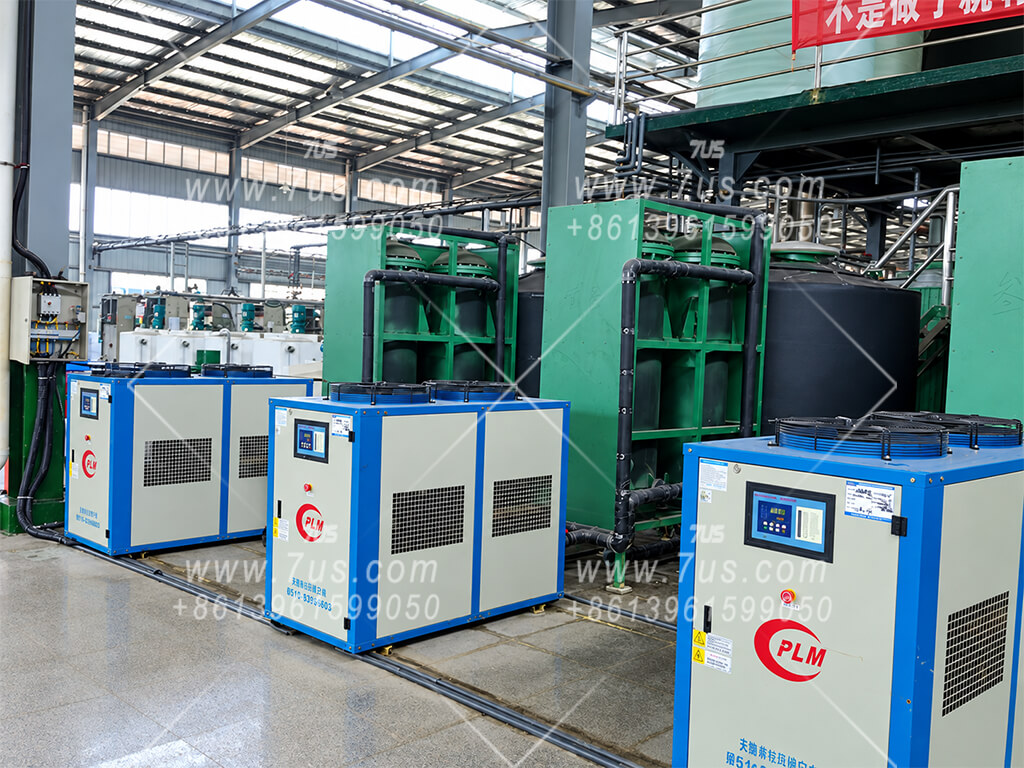
The insulated tanks help limit heat gain after cooling. Tank volume and cooling duty must allow the standby tank to be ready before the supplying tank runs out.

Gel battery electrolyte

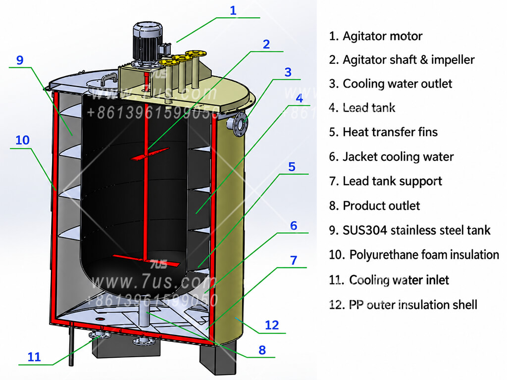
Multi-layer jacketed gel electrolyte cooling tank

Gel electrolyte with a high colloidal-additive content can solidify after a shutdown. Material left in graphite tubes may cause blockage and be difficult to remove. A jacketed tank provides an accessible arrangement for cleaning and maintenance.

Three-layer tank construction
Inner assemblyA lead tank contacts the electrolyte. A stainless steel support shell maintains its shape: SUS304 is standard; SUS316 is available as a project option.
Second layerA PP plastic tank surrounds the inner assembly. Cooling water or chilled water circulates in the jacket between them; heat transfer fins support heat exchange.
Outer layerA third plastic tank forms the outer enclosure. Polyurethane foam insulation fills the gap between the second and third tanks to limit heat gain.

An agitator supports mixing during cooling. The accessible tank opening helps with removal of solidified gel and inspection after shutdown. Final materials and cleaning arrangements are confirmed for the actual formulation.

Match the production temperature

Specify the electrolyte temperature required at the use point, inlet temperature, formulation and production demand. Cooling is configured for the battery process rather than a fixed universal setpoint.

Match the cooling supply

Confirm available cooling-water or chilled-water temperature and flow, ambient conditions and operating hours. These inputs determine cooling duty and whether a separate chiller is required.

Match capacity & investment

Coordinate cooling time, tank capacity and downstream consumption. Choose the stainless steel option and equipment configuration around the agreed process requirements and project budget.

These downstream cooling systems are separate from the dilution unit’s heat-removal circuit. Their inclusion, cooling capacity, tank construction and control interfaces are defined in the quotation and technical agreement.

Cooling System Applications & Construction

Single-tank units, alternating dual-tank systems and gel electrolyte cooling installations.

The one-hour cycle shown for the rapid cooling system is project-specific. Actual cooling time depends on acid volume, inlet and target temperatures, formulation and available refrigeration capacity.

Discuss Your Acid Preparation Project

Contact 7US — Jiangsu Erhuan Environmental Technology Co., Ltd. — for a custom acid dilution and cooling configuration. Send your feed-acid and target specifications, batch volume, daily demand, required electrolyte temperature and available cooling utilities.

Product image