
Foundries
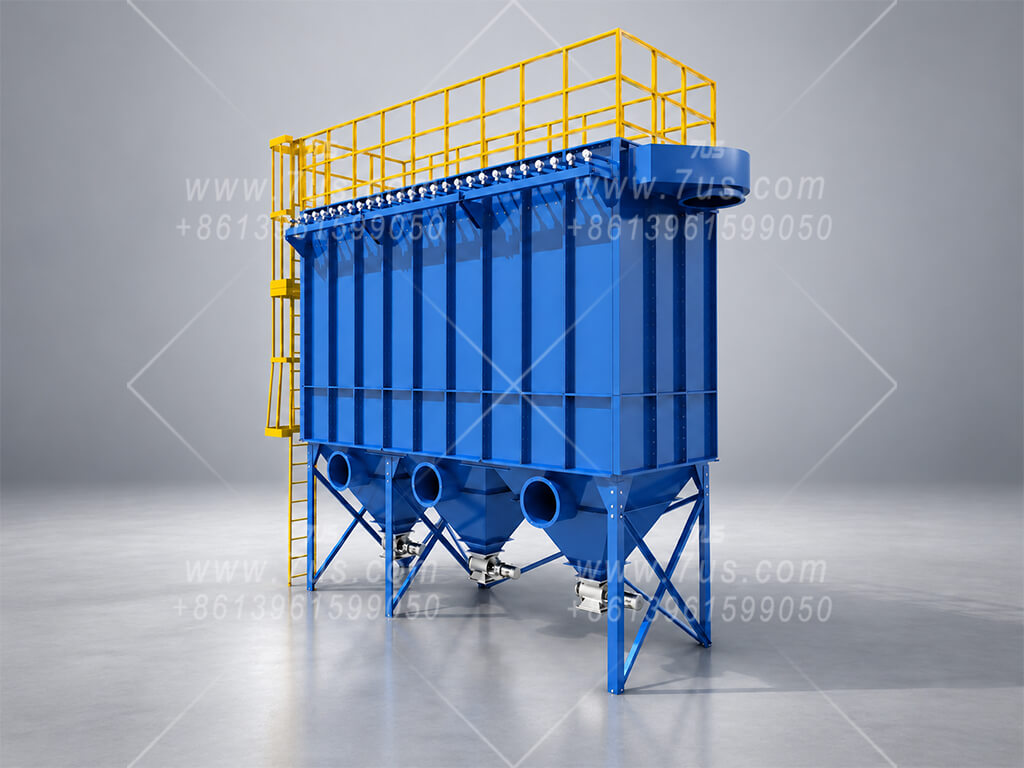
Capture dust from sand handling, shakeout and other foundry operations with a configuration matched to the dust and gas temperature.
The EHRBT is a modular bag filter dust collector with vertical round filter bags, automatic pulse-jet cleaning and flexible layouts for industrial dust collection projects.
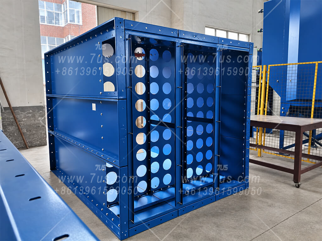
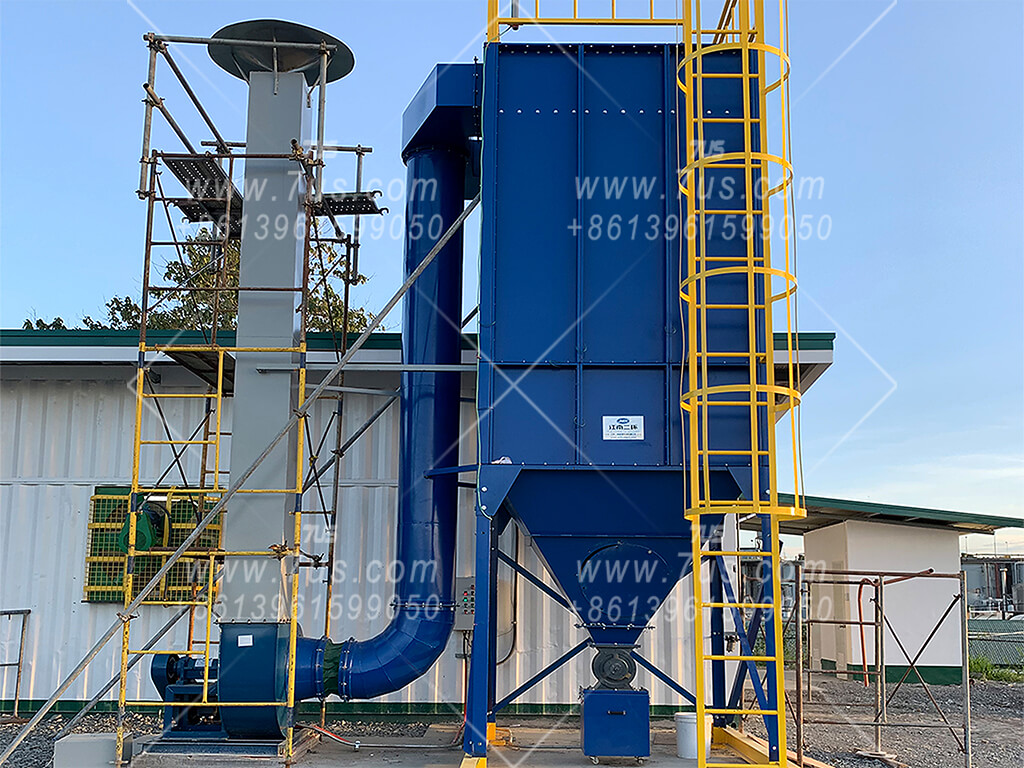
Two 7US project photos show the collector before filter installation and after installation on site. Circular filter mounting openings sit within the modular housing; the completed unit includes a hopper, access ladder and connected ductwork. The arrangement is configured for each project.
Follow the airflow and cleaning path through the illustrated collector. Numbered callouts identify the principal components of this configuration.
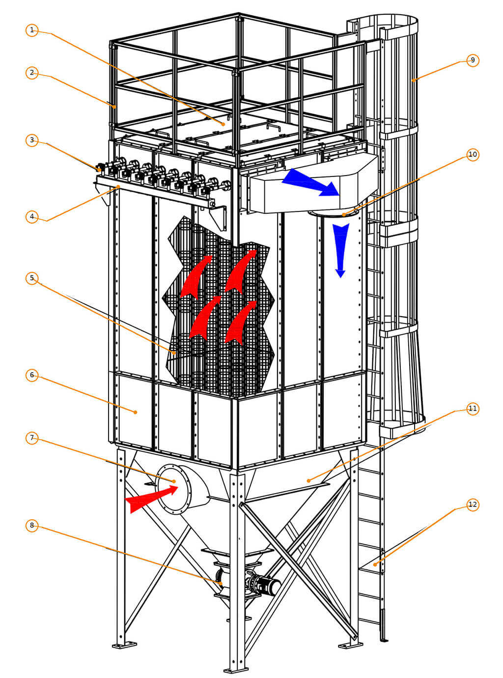
Dust-laden air enters at the lower inlet (7) and moves through the collector toward the round filter bags (5).
Air passes through the filter media while dust is retained on the bag surfaces. Filtered air is directed to the clean-air outlet (10).
Pulse valves (3) release compressed air from the air header (4) to clean the bags. Dislodged dust falls into the hopper (11) and exits through the discharge valve (8).
The inspection door (1) provides access to the upper section. The safety railing (2) and access ladder (9) support routine inspection of this illustrated configuration.
Round filter bags are supported by wire cages and fitted into the openings of the tube sheet. The bag, cage and mounting details are selected to suit the collector and the operating conditions.
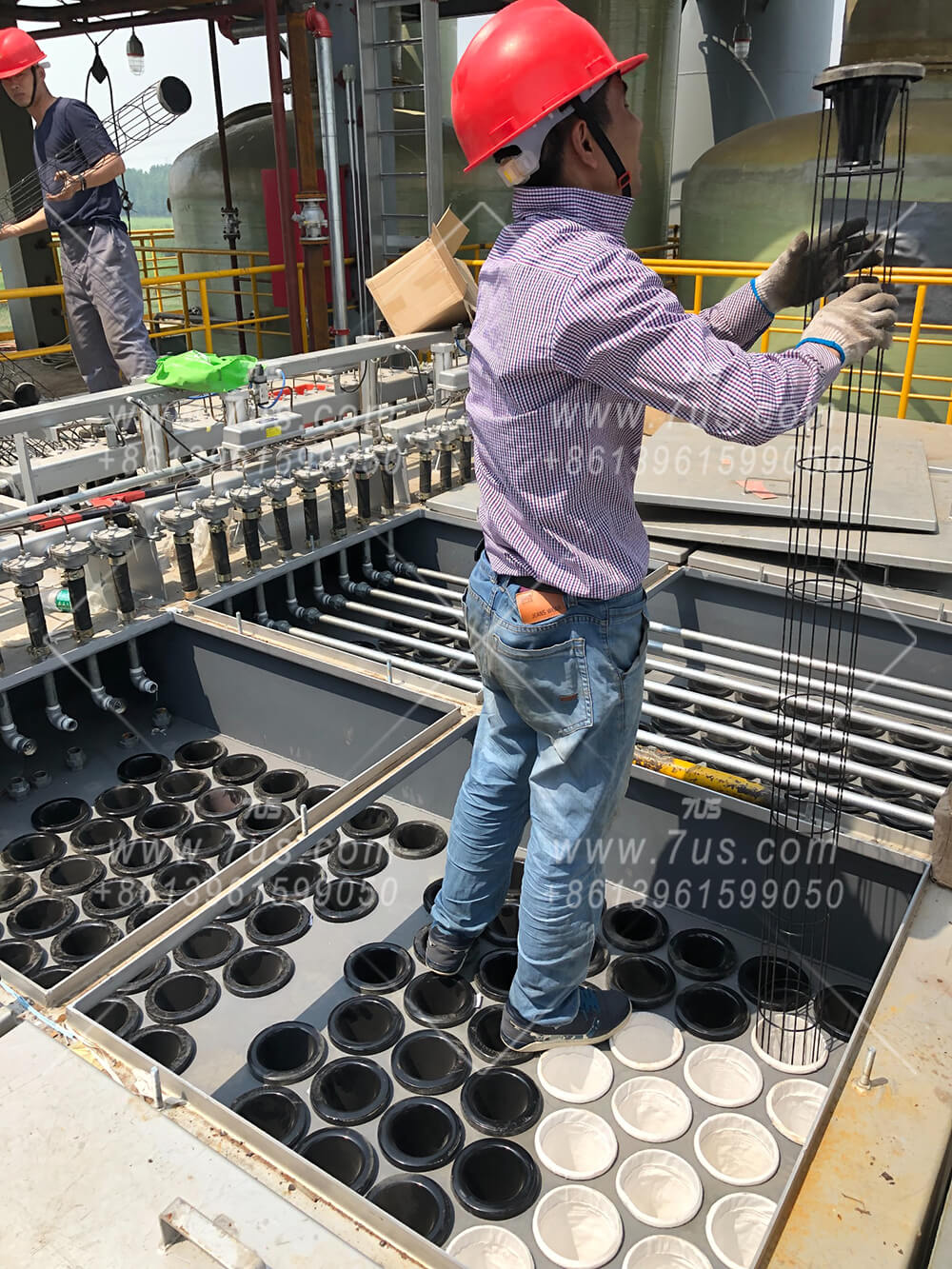
Dust is retained on the outside of the filter fabric as air passes through the bags. The media is chosen for the actual dust, operating temperature and process conditions.
A wire cage supports each bag and helps it maintain its shape during filtration and pulse cleaning. Cage length and diameter must match the selected bag and the collector layout.
The photo shows the bag openings arranged across the tube sheet. The bag connection and cage fit are checked against the opening size so the filter assemblies seat correctly.
Technicians position each bag and its support cage from the clean-air side. The white fabric bags and the upright cages in the photo show different stages of installation.
Round bags and cages need clear access above the tube sheet for installation and later replacement. The required maintenance space depends on the bag length and the project arrangement.
Start with the dust and operating conditions, then choose the filter media and design air-to-cloth ratio. Calculate the required filter area from the project airflow before deciding how many base modules fit the available site space.
Confirm dust properties, loading, temperature and process conditions before selecting the filter media.
Use the required airflow and the selected design filtration velocity to establish the required filter area.
Compare bag length, module count, site dimensions and overhead space for bag replacement.
Standard bag diameter: Ø155 mm
| Bag size | Bags | Nominal filter area |
|---|---|---|
| Ø155 × 2.0 m | 54 | 52.6 m² |
| Ø155 × 2.2 m | 54 | 57.8 m² |
| Ø155 × 3.0 m | 54 | 78.9 m² |
Standard bag diameter: Ø155 mm
| Bag size | Bags | Nominal filter area |
|---|---|---|
| Ø155 × 2.0 m | 81 | 78.9 m² |
| Ø155 × 2.2 m | 81 | 86.8 m² |
| Ø155 × 3.0 m | 81 | 118.3 m² |
Nominal area is the cylindrical bag side area: π × bag diameter × bag length × bag count. These values are reference geometry, not a guaranteed effective area or airflow rating; final selection depends on bag construction, media and operating conditions.
Other bag diameters and lengths up to 8 m can be evaluated for project-specific designs. Such sizes are outside the standard table and require confirmation of the collector layout, cleaning system and installation and replacement clearance.
For a quick preliminary estimate, use one 81-bag module with Ø155 × 3.0 m bags as the reference building block. Combine modules to increase the nominal filter area while checking the project layout and maintenance clearances.
| Modules | Bags | Nominal area | Reference airflow |
|---|---|---|---|
| 1 | 81 | 118.3 m² | 10,000 m³/h |
| 2 | 162 | 236.7 m² | 20,000 m³/h |
| 3 | 243 | 355.0 m² | 30,000 m³/h |
| 4 | 324 | 473.3 m² | 40,000 m³/h |
| 5 | 405 | 591.6 m² | 50,000 m³/h |
| Modules | Bags | Nominal area | Reference airflow |
|---|---|---|---|
| 6 | 486 | 710.0 m² | 60,000 m³/h |
| 7 | 567 | 828.3 m² | 70,000 m³/h |
| 8 | 648 | 946.6 m² | 80,000 m³/h |
| 9 | 729 | 1,065.0 m² | 90,000 m³/h |
| 10 | 810 | 1,183.3 m² | 100,000 m³/h |
Airflow figures are proportional reference values for a preliminary comparison, not fixed ratings. Select filter media and design filtration velocity for the actual dust and operating conditions before confirming the effective area, module count, fan and final airflow. The ten rows are examples and do not define a maximum number of modules.
Follow one high-temperature round baghouse from housing fabrication and insulation through assembly, transport and installation at the project site.
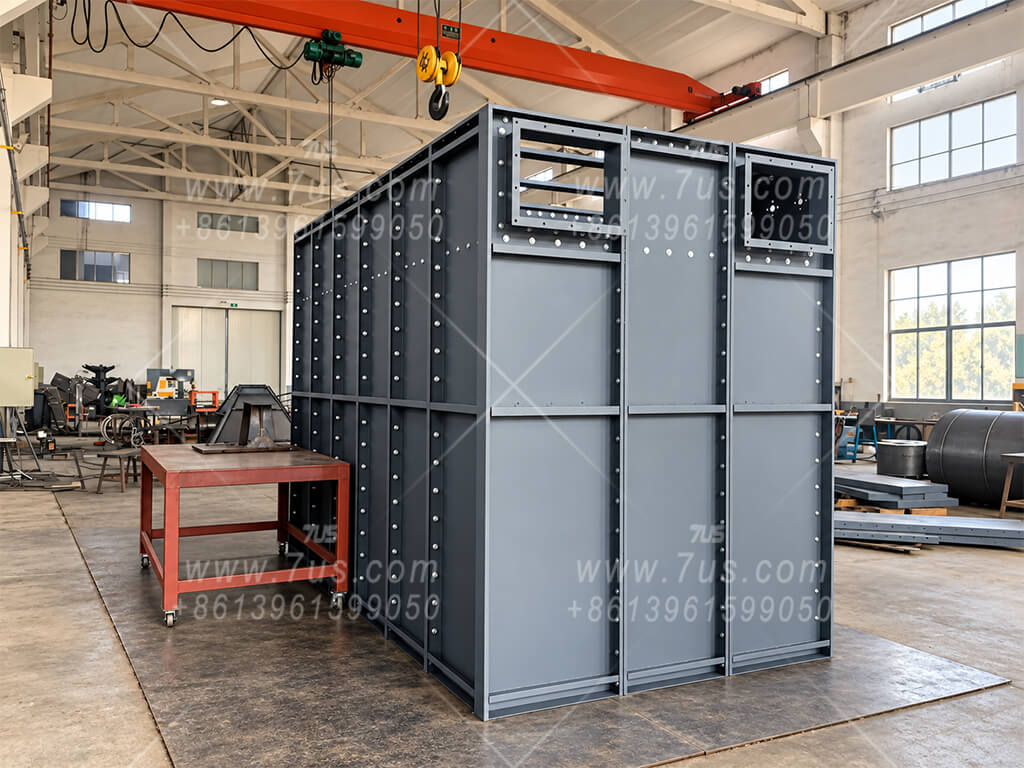
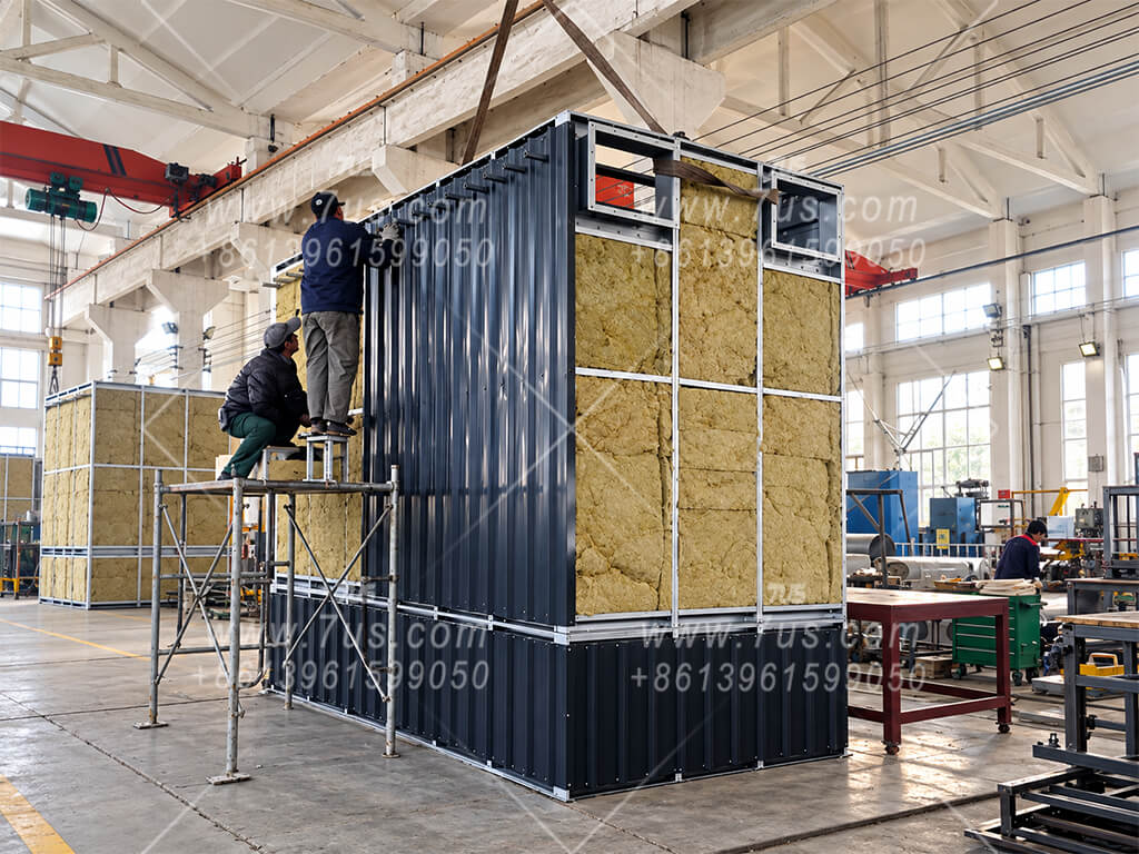
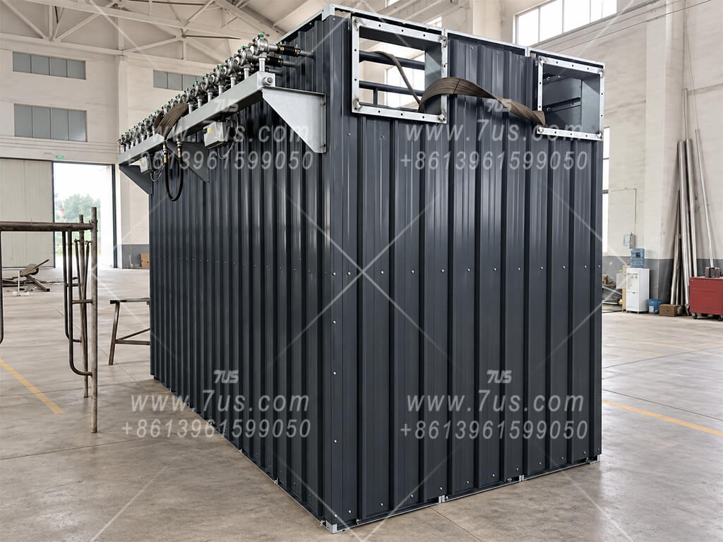
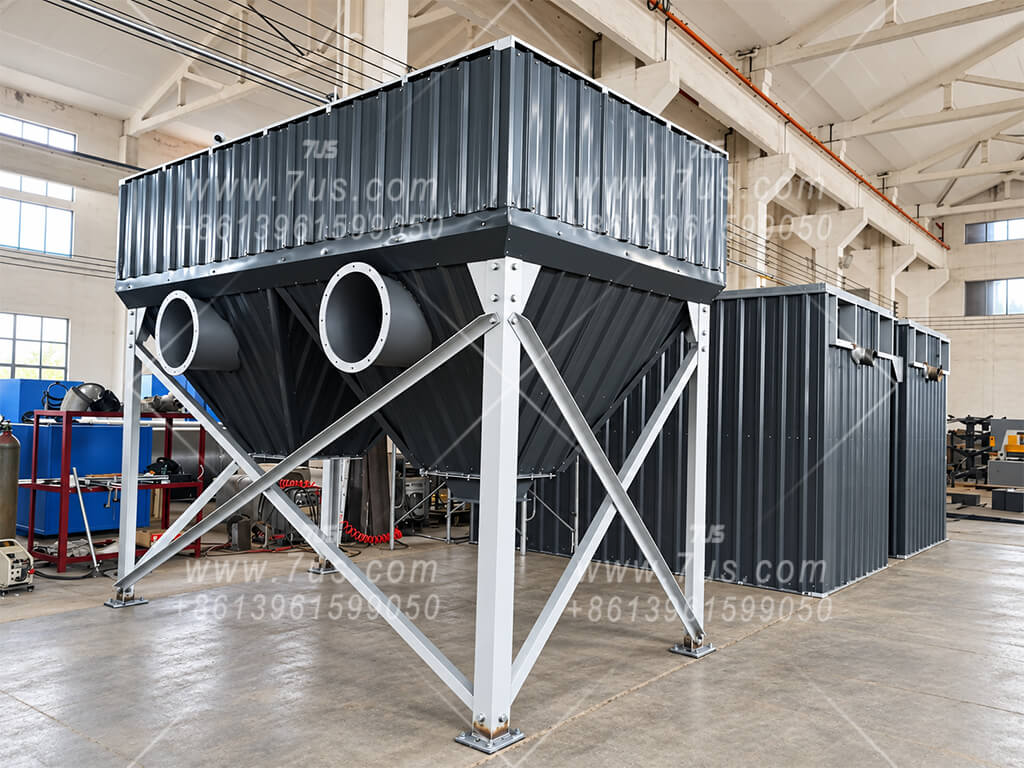
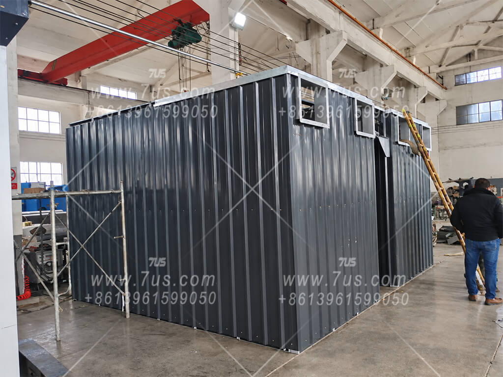
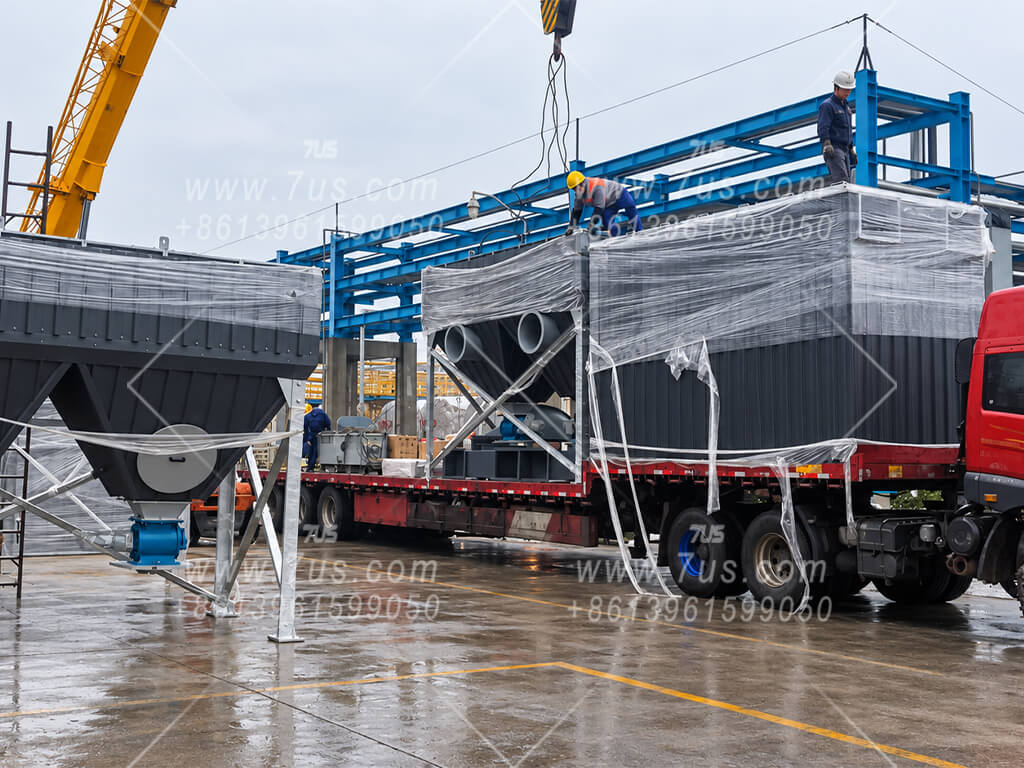
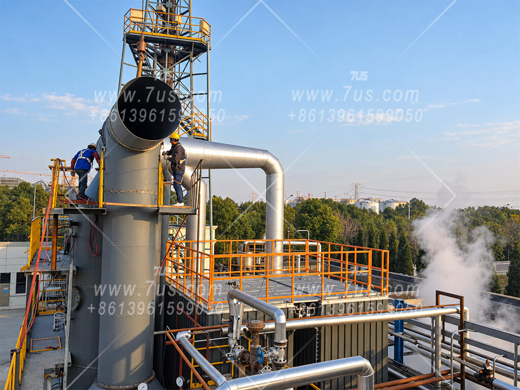
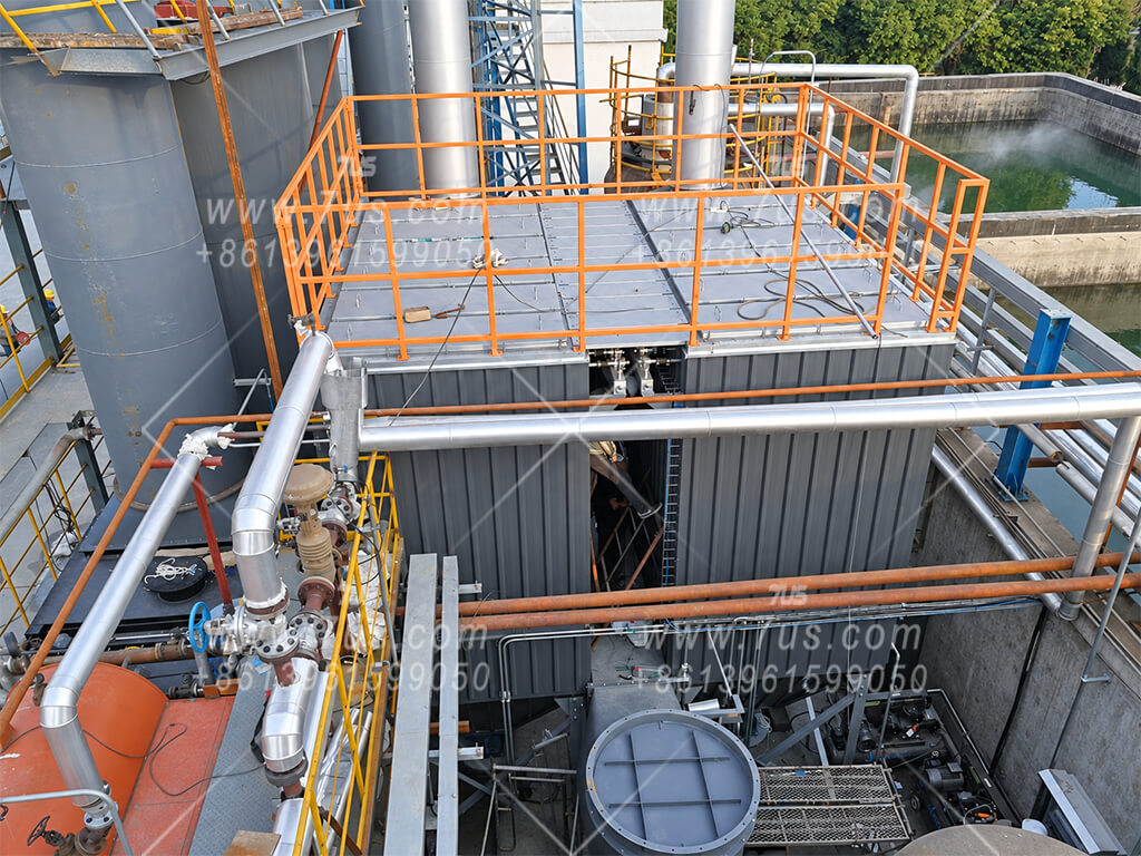
All eight photos show the same equipment from factory work through on-site installation. Click a photo to enlarge.
Modular round baghouses can be configured for a range of industrial dust and process exhaust streams. Filter media, air-to-cloth ratio and equipment details are selected for the actual operating conditions.
Capture dust from sand handling, shakeout and other foundry operations with a configuration matched to the dust and gas temperature.
Collect particulate from selected metal production and material handling points, with inlet conditions reviewed for each process.
For suitable boiler exhaust streams, specify the filtration system around the measured inlet temperature, fuel ash and moisture.
Filter particulate from suitable kiln-related exhaust after checking temperature peaks, gas composition and upstream treatment.
Collect fine dust from calcium carbonate grinding, classifying and conveying, as well as suitable cement and mineral handling points.
Match bag media and construction to the powder properties, process gas and any required corrosion or static control.
Collect wood dust at suitable extraction points, with fire and explosion protection assessed for the specific process.
Collect dust at ore crushing and coal belt conveyor transfer points, with filtration and safety measures selected for each material and process.
Application examples are not fixed equipment ratings. Confirm dust characteristics, temperature range, humidity, gas composition and required safety measures before selecting filter media, filtration velocity and module count.
Select components around the actual dust, gas temperature, humidity, site requirements and maintenance plan. The items below are project options, not standard equipment on every baghouse.
Carbon steel, SS304 stainless steel or SS316 stainless steel, selected for the process environment.
Housing and hopper plate thickness can be specified to suit the equipment size and project requirements.
Epoxy glass-flake mastic lining can be specified for suitable corrosion conditions.
Inspection platforms, guardrails and access ladders can be included as required by the site layout.
Polyester needle felt, membrane-coated and antistatic bags are available. For higher-temperature duty, consider suitable PPS or aramid media after reviewing temperature peaks and gas chemistry.
Select bag finish and cage construction to suit dust release, corrosion exposure and service life. Standardized Ø155 bags and 2.0, 2.2 or 3.0 m lengths remain the selection reference; other sizes can be specified.
Insulation and exterior cladding may be specified for suitable hot-gas installations, with attention to heat loss, condensation risk and safe access.
Pulse valves, compressed-air headers and cleaning controls can be configured for the selected bag arrangement and operating conditions.
Select a conventional hopper or a trough-shaped (boat-type) hopper to suit the equipment layout. A screw conveyor can collect dust or ash along the trough; rotary airlocks or double-flap valves can be specified at discharge as required.
A pressure gauge or sensor provides a practical indication of filter loading and supports inspection or cleaning control.
Fan selection and variable-frequency control can be coordinated with the required airflow, system resistance and operating range.
Depending on the dust hazard assessment, specify antistatic media, grounding, explosion venting or flameless venting as applicable to the project.
Configure pulse sequencing and differential-pressure inputs. Supply voltage and frequency (Hz) can be specified for the destination country, and electrical component brands can be designated. Additional monitoring or touchscreen controls are available by project.
Final selections are confirmed against the process conditions, site requirements and project engineering. Explosion-protection components are specified according to the applicable dust hazard assessment.
Send your operating conditions and available space so we can review the filter media, required filter area and module arrangement.
Describe the process, dust material and loading, moisture, and any known combustible or corrosive properties.
Provide the required airflow, normal and peak inlet temperatures, operating hours and outlet emission requirements.
Share the available footprint and height, installation location, duct connections and maintenance access. Site photos or drawings are helpful.
Tell us your preferred dust discharge arrangement, housing material, power supply, fan and control requirements.
Final filter media, filtration velocity, bag length and module count are confirmed for your application.
Send Your Project Requirements