
Use the Available Height
Longer cartridges provide more area per cartridge. Match the housing height to the selected length and retain the lower inlet and settling space.
Modular vertical cartridge dust collectors with front-access, drawer-like cartridge replacement, eccentric cam clamping and automatic pulse-jet cleaning.
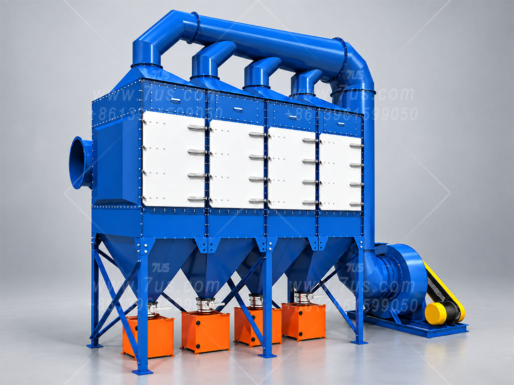
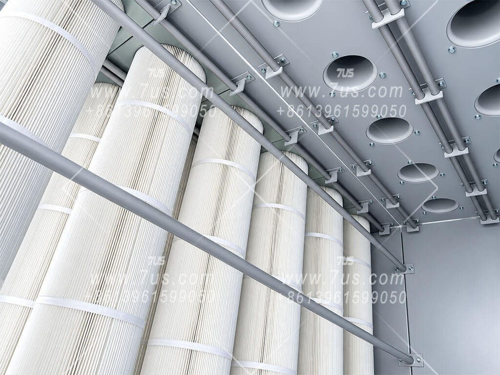
The cartridges are installed vertically below the tube sheet, but routine replacement is performed entirely from the front of the collector. A guided hanging structure, standardized cartridge top plate and eccentric cam clamping mechanism allow each cartridge to be pushed into position in a drawer-like motion without dismantling the clean-air chamber above.
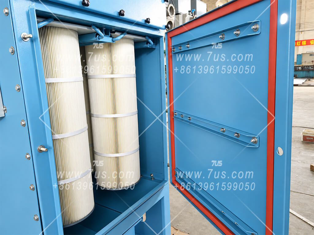
Cartridge replacement does not require removal of the venturis or pulse pipes above the tube sheet. The operator works from the front service opening, releases the eccentric cam clamping mechanism, slides the cartridge along the guide structure, and locks it back into its designed position after replacement.
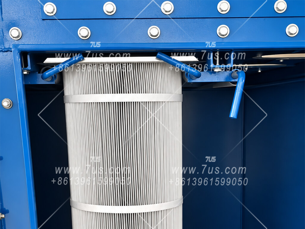
These production photographs show the clamping detail, the untouched clean-air-side components above the tube sheet, and the fixed geometry that keeps each cartridge centered below its corresponding opening.
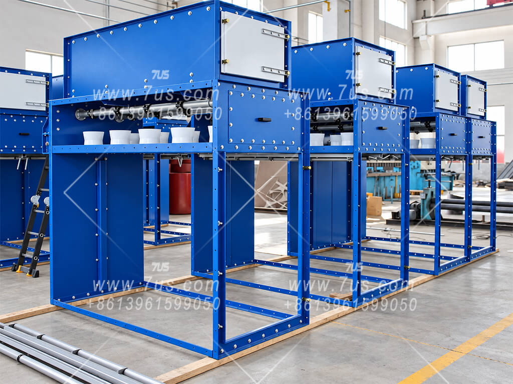
The vertical cartridge layout is designed so dust-laden air can enter below the cartridge section, where the larger internal cross-section reduces velocity before the finer dust reaches the filter media. This creates a useful settling and airflow-conditioning zone ahead of filtration.
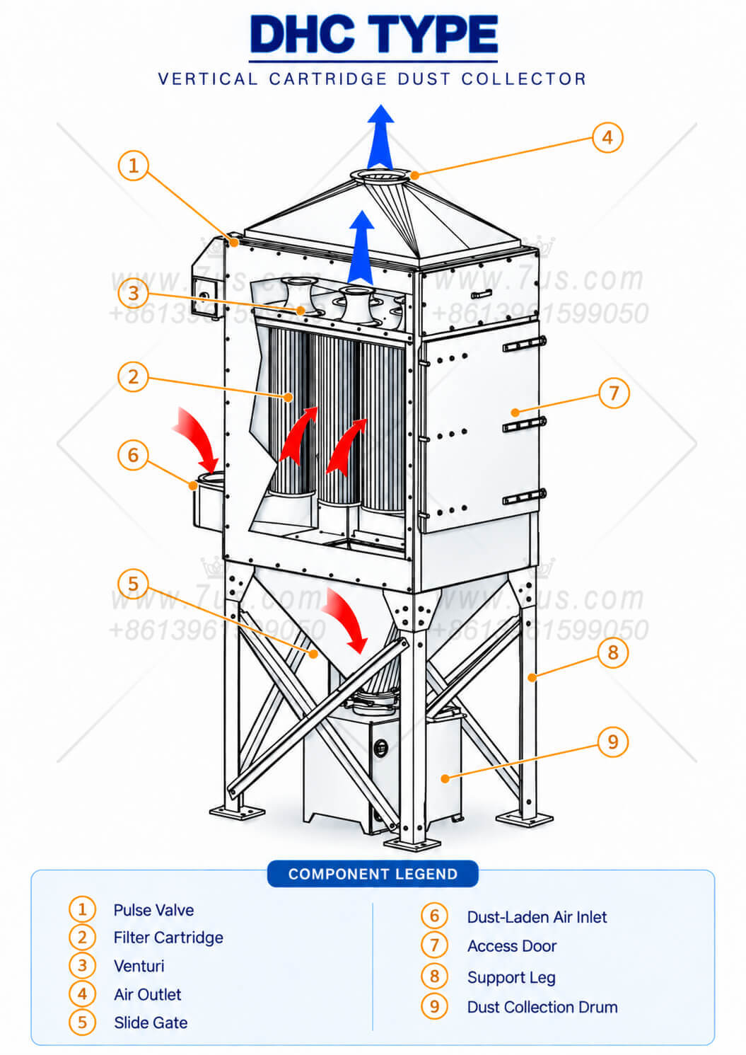
High-velocity dust-laden air is introduced below the cartridges. Once it enters the larger collector body, the available flow area increases and air velocity drops, reducing direct impact on the filter media and giving heavier particles an opportunity to fall toward the hopper before the finer fraction moves upward to the cartridges.
The airflow principle remains the same, while inlet and clean-air outlet positions can be adapted to site space, duct routing and system layout. Large modular systems normally benefit from a dedicated lower inlet / air-distribution section; height-limited layouts may use side-entry arrangements with internal baffles where required.
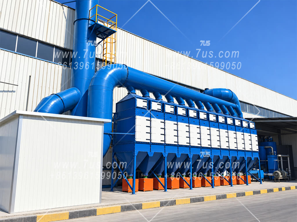
Inclined cartridges are a proven industrial arrangement, but their upper-facing surface can still provide an area where released dust may settle again after pulse cleaning. A fully vertical cartridge removes this upward-facing dust-resting surface.
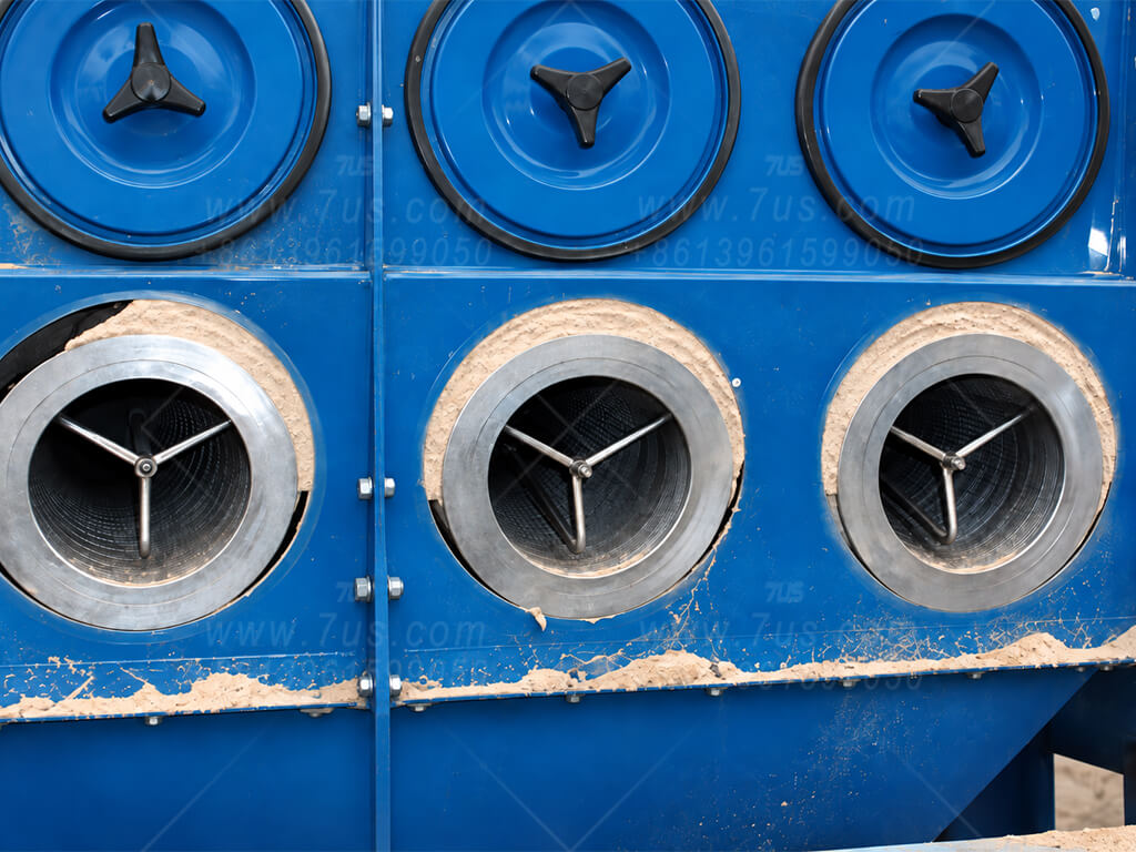
The photograph shows an actual inclined-cartridge collector after service. Dust behavior varies with particle characteristics, loading and pulse-cleaning conditions, but the inclined geometry still leaves an upper-facing cartridge surface where part of the released dust can remain or re-settle.
Define the duty. Calculate the filter area. Then fit it to the site. Select suitable media and design filtration velocity for the dust and operating conditions. Use the required airflow to calculate area, then choose cartridge length and module arrangement to suit the available space.
A model number is not a fixed airflow rating. The design filtration velocity must be selected for the duty before the required filter area is calculated.
Review the dust type and inlet concentration, temperature, moisture and any corrosive or combustible characteristics. Confirm the filtration duty and required airflow before choosing the media and design filtration velocity.
Filter area = airflow ÷ (60 × design filtration velocity)
Once the area requirement is known, choose how to accommodate it. Cartridge length, cartridges per module and the number of side-by-side modules provide three different layout choices.
Longer cartridges provide more area per cartridge. Match the housing height to the selected length and retain the lower inlet and settling space.
Each module has two front-to-back cartridge rows. More cartridges in each row require a deeper module.
Use more modules to provide additional area, or combine shallower modules where site depth is restricted but width is available.
4 cartridges / module
2 rows × 22 cartridges front to back in each row
6 cartridges / module
2 rows × 33 cartridges front to back in each row
8 cartridges / module
2 rows × 44 cartridges front to back in each row
10 cartridges / module
2 rows × 55 cartridges front to back in each row
12 cartridges / module
2 rows × 66 cartridges front to back in each row
With the same cartridge length, media and effective area per cartridge, different module combinations can provide the same total filter area. Select the layout that fits the site.
Use one DHC8 where depth is available. Where depth is restricted but width is available, place two DHC4 modules side by side.
Use one DHC12 where depth and transport permit. Two DHC6 modules provide an alternative when a shallower layout or different shipping arrangement is needed.
The same DHC8 module concept can use eight Ø324 mm cartridges of different lengths. At the confirmed media specification, longer cartridges increase area without adding cartridges.
14 m² / cartridge
112 m² total / DHC8Baseline area16.8 m² / cartridge
134.4 m² total / DHC820% more area21 m² / cartridge
168 m² total / DHC850% more areaThis example demonstrates the selection method. It assumes that the process has already been assessed and a design filtration velocity of 1.0 m/min has been selected.
Required airflow: 6,000 m³/h
Selected design filtration velocity: 1.0 m/min
Assuming a confirmed design velocity of 1.0 m/min:50,000 ÷ (60 × 1.0) ≈ 833.3 m²
7US polyester-based Ø324 mm cartridges. Reference airflow = total filter area × 1.0 m/min × 60. Values below are for one base module, not a fixed rating for every duty.
| Base module | Cartridges per module | 1000 mm · 14 m² / cartridge | 1200 mm · 16.8 m² / cartridge | ||
|---|---|---|---|---|---|
| Total area (m²) | Reference airflow (m³/h) at 1.0 m/min | Total area (m²) | Reference airflow (m³/h) at 1.0 m/min | ||
| DHC4 | 4 | 56 | 3,360 | 67.2 | 4,032 |
| DHC6 | 6 | 84 | 5,040 | 100.8 | 6,048 |
| DHC8 | 8 | 112 | 6,720 | 134.4 | 8,064 |
| DHC10 | 10 | 140 | 8,400 | 168 | 10,080 |
| DHC12* | 12 | 168 | 10,080 | 201.6 | 12,096 |
DHC6 and DHC10 identify base modules. A complete collector code also includes the total cartridge count and cartridge length code.
Send the dust/process details, inlet concentration, required airflow and available height × width × depth. Include temperature, moisture, corrosive components and any explosion-protection requirements where applicable.
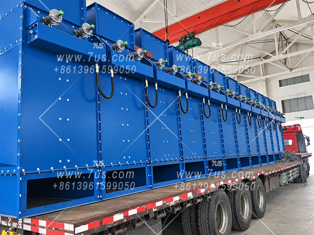
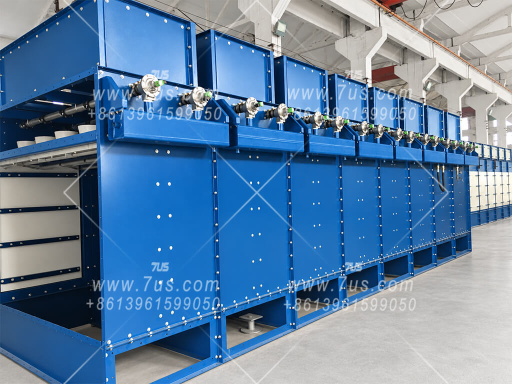
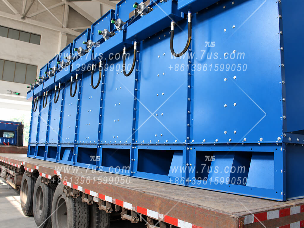
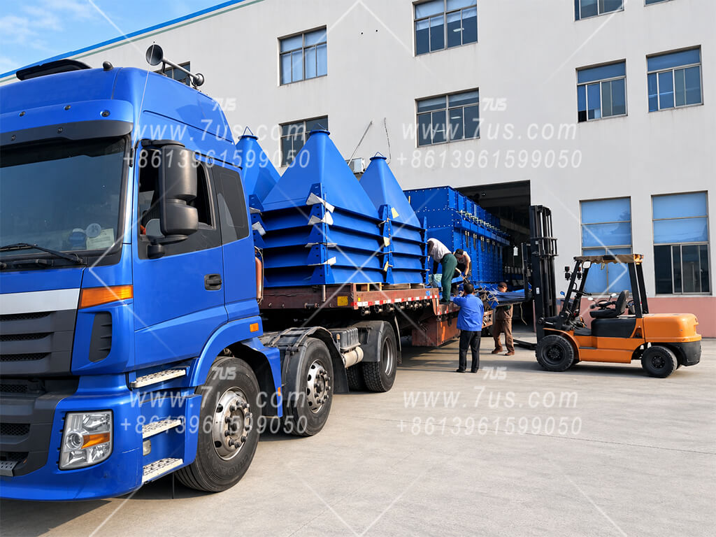
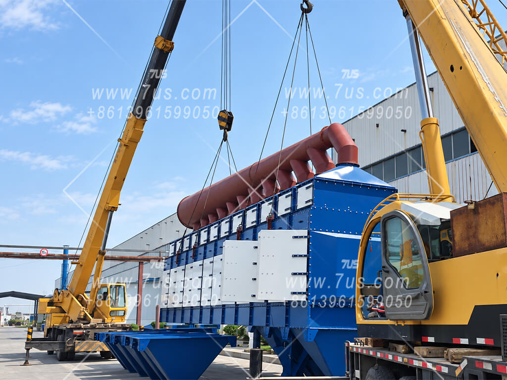
Large vertical collectors are prepared as transport-ready modular assemblies before dispatch. The final split between collector modules, hopper / support sections, fan packages and external ductwork is confirmed around transport, lifting access and the site installation plan.
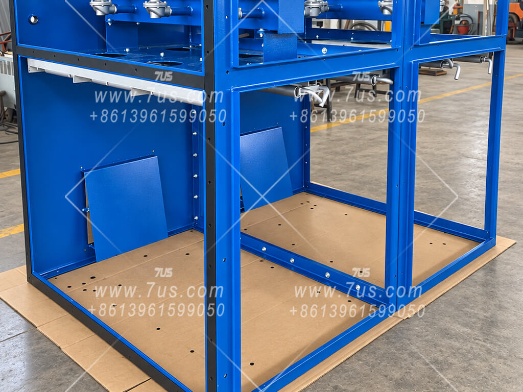
Representative 7US vertical modular collector projects. The images show factory trial assembly, dispatch and field installation across different project configurations. Optional secondary final filtration is selected only where the emission target or return-air requirement calls for it.
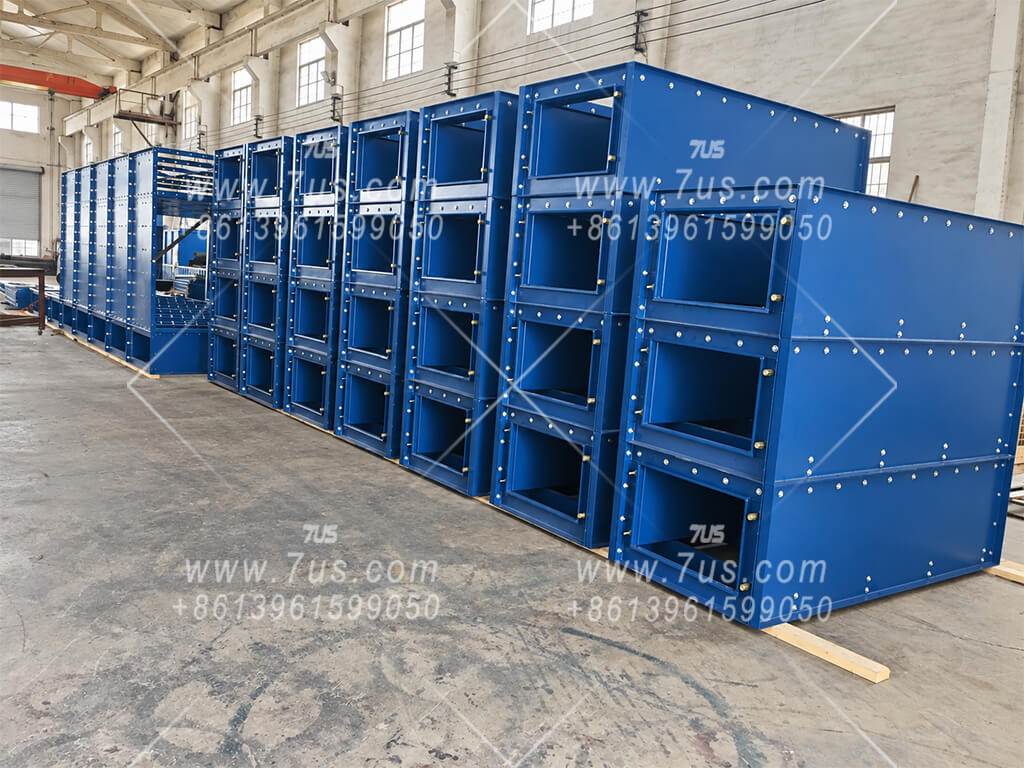
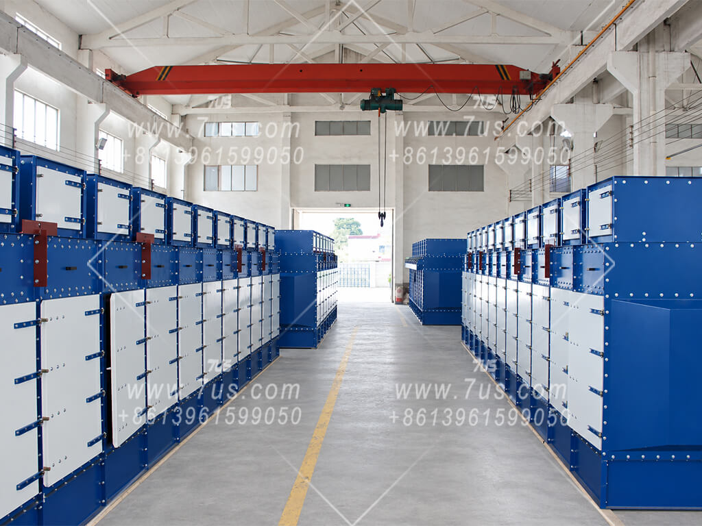
Trial-assembled modules simplify transport, lifting and site installation.
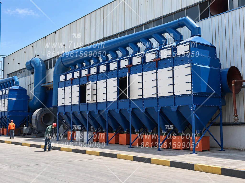
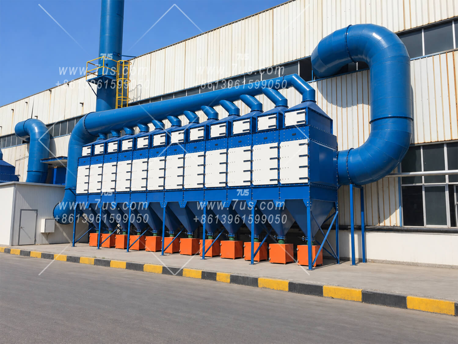
The DHC collector body can be supplied separately or as a package with a fan, motor, electrical controls and selected safety components.
Module arrangement, cartridge length and filter media are selected around the required airflow, dust characteristics and available space. A secondary HEPA stage can be included where emission limits or return-air requirements call for it.
Share existing drawings and duct connections so we can confirm the interfaces and quotation scope. Detailed GA and DWG project drawings can be prepared after the configuration and order requirements are confirmed.