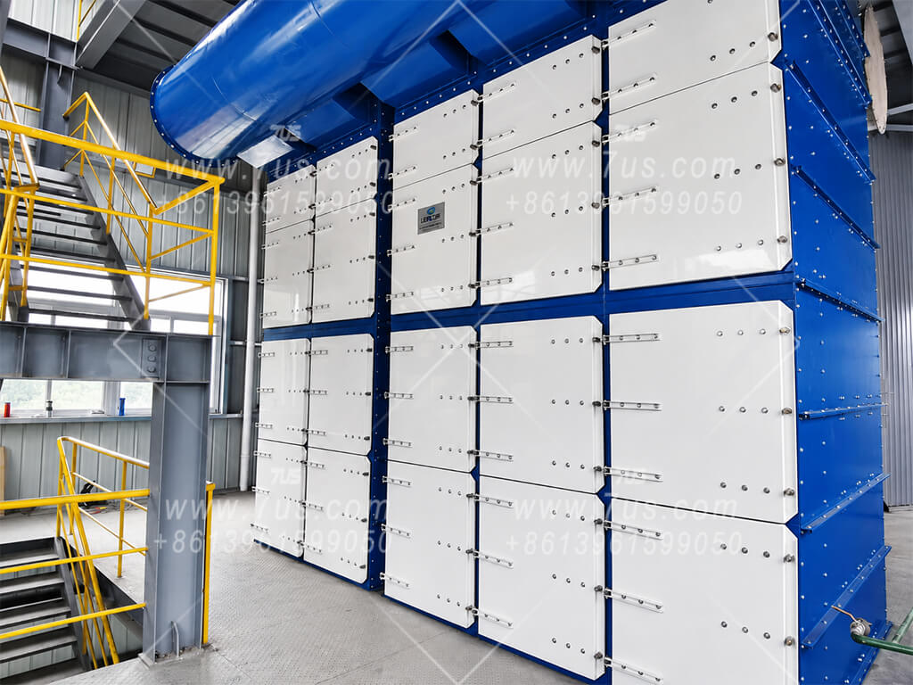
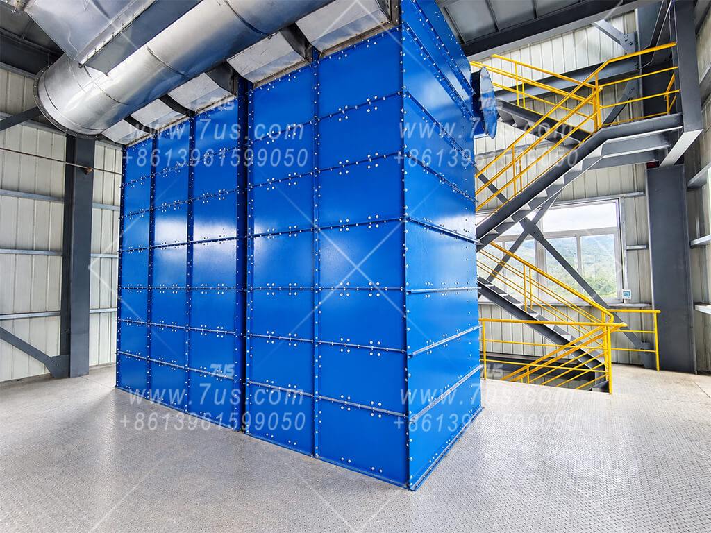
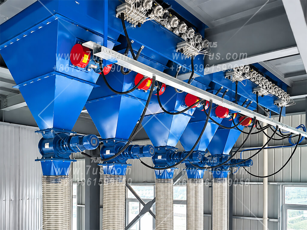
04 · FIT THE AREA TO THE SITEThe Required Area Can Be Arranged in Different Heights, Widths and Depths
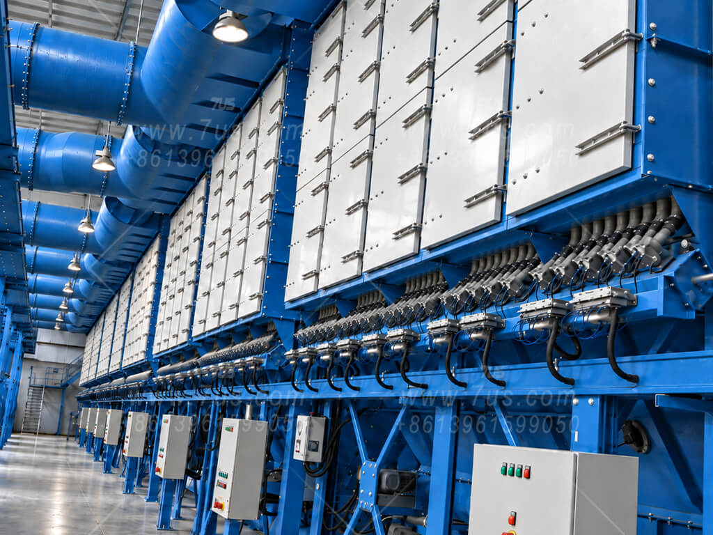
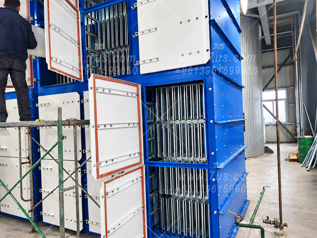
Once the effective area is known, choose the geometry around the actual installation envelope. The same total filter area can be arranged as a taller single module or as several lower modules placed side by side.
HEIGHT LIMITEDFewer layers, more module columnsReduce vertical levels and add horizontal modules while preserving the required total filter area.
DEPTH LIMITEDUse shorter bagsUse 1.5 m or a custom shorter bag, then recover the required area through layers or additional module columns.
WIDTH AVAILABLEExpand horizontallyAdd standard module columns in parallel without increasing the number of vertical layers.
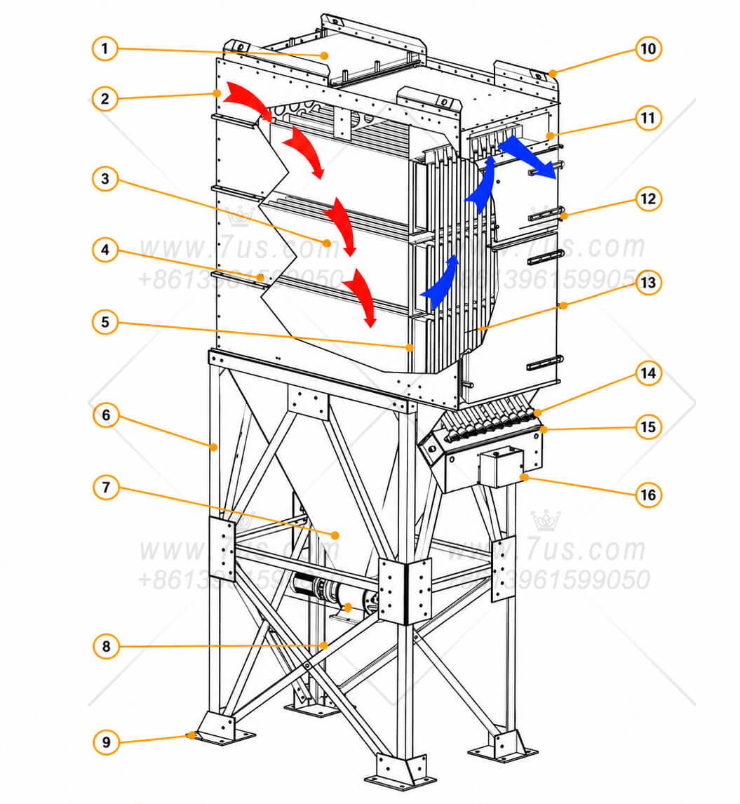
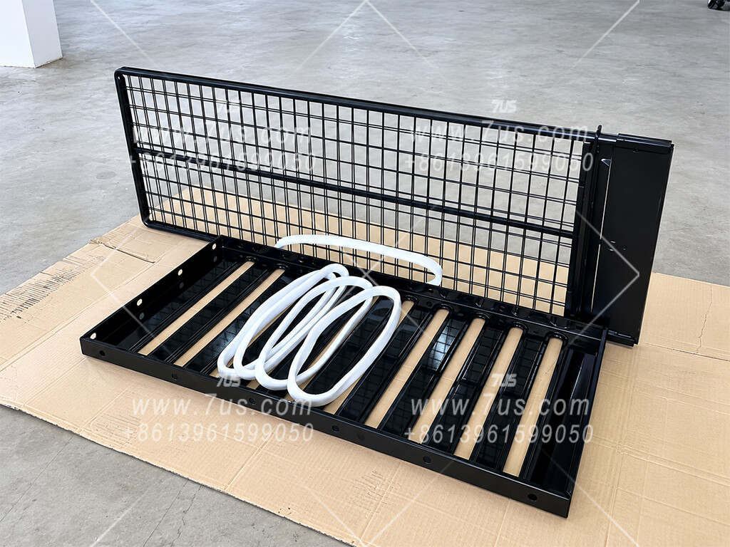
CUSTOM GEOMETRYAdjust the building block10-slot rows and 1.5 / 2.0 m bags are mainstream formats, not hard design limits.
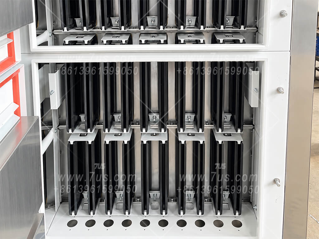
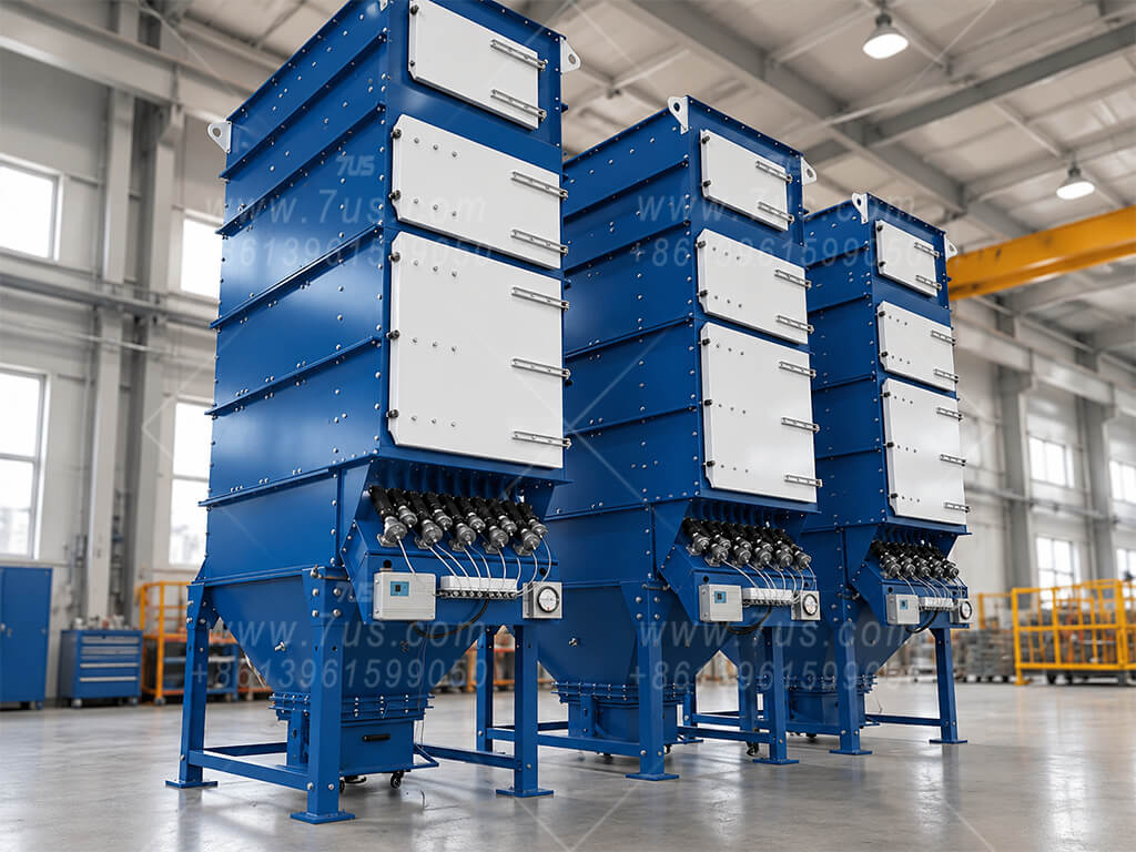
Same filter area, different physical layoutsAbstract example using 1.5 m bags: both layouts provide about 120 m² of effective filter area.
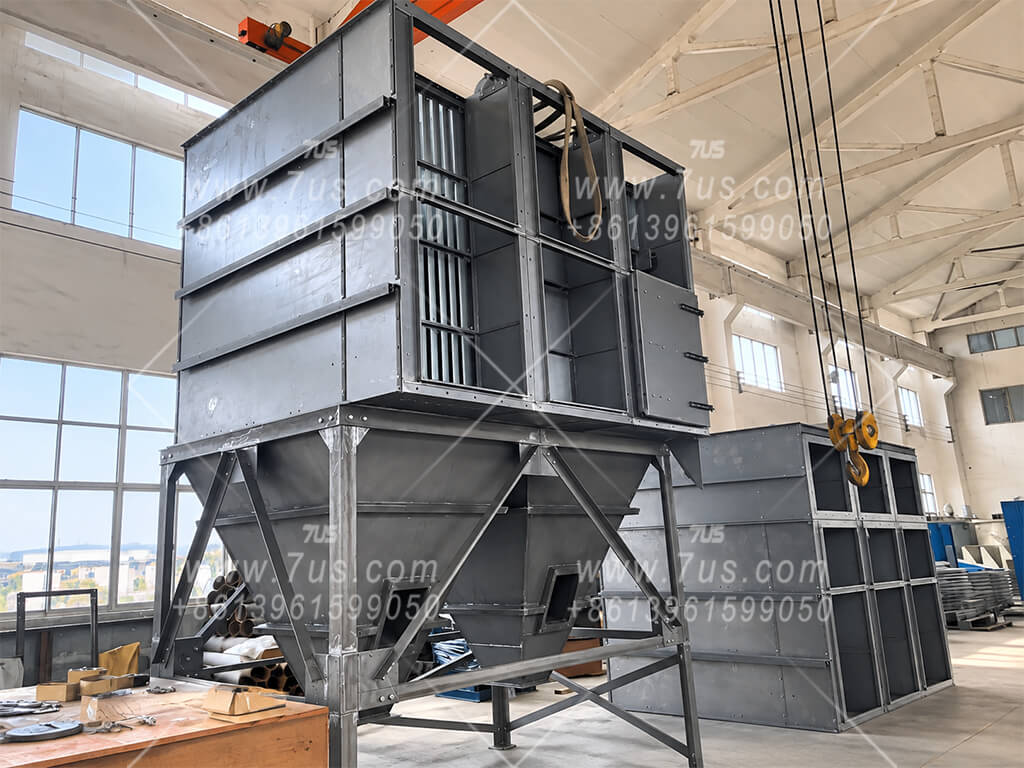
1 × EHFBC1/8/15One taller module · ≈120 m²
=
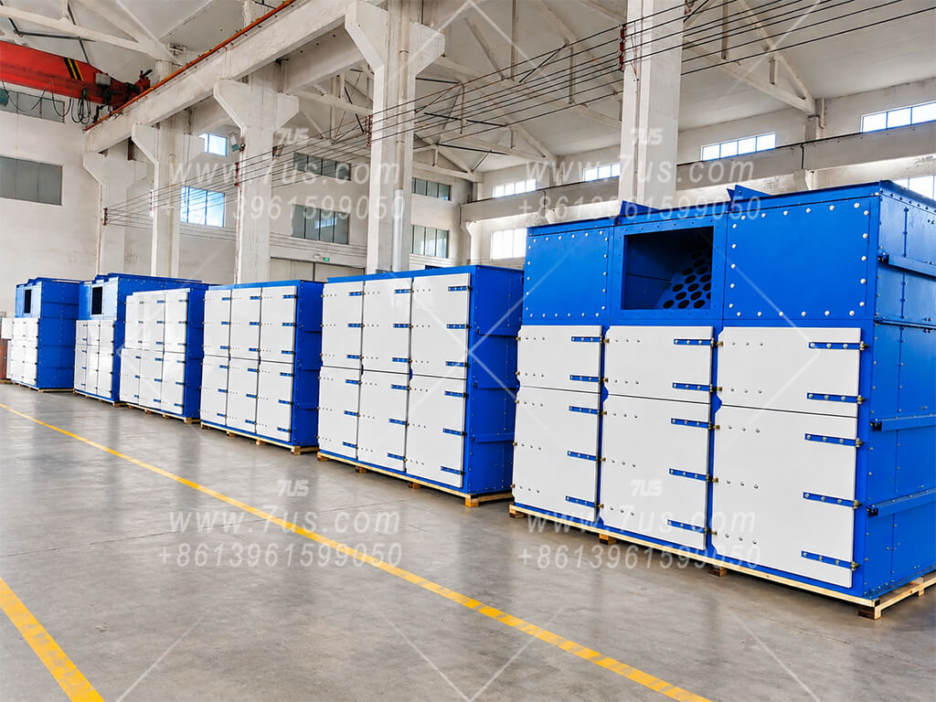
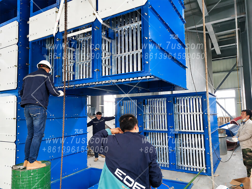
2 × EHFBC1/4/15Two lower modules · ≈120 m² total
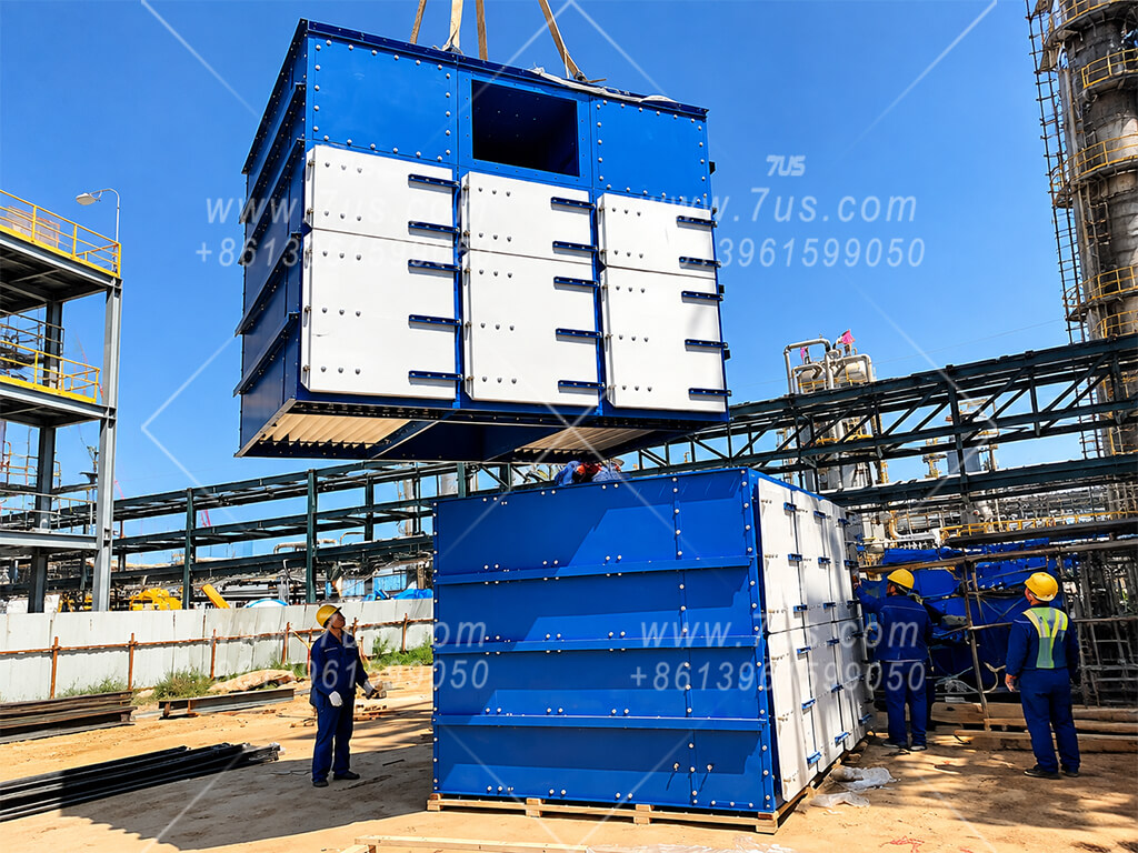
Cost-layout principle: where installation space is not constrained, fewer larger modules are generally more economical than splitting the same filter area into more smaller modules. Multiple modules duplicate items such as hoppers, discharge devices, pulse-cleaning hardware, cabinet / connection structures and site assembly work. When height, width, depth, transport or lifting conditions are constrained, the layout is adjusted to suit the project.
ILLUSTRATIVE 10,000 m³/h GENERAL-DUST DUTYAt 1.2 m/min → about 139 m² requiredThe target area can be met by more than one physical arrangement. The final choice depends on the available height, depth, width and preferred maintenance layout.
BUILD THE AREA, NOT A FIXED AIRFLOW MODELChoose the module geometry only after the required filter area is known.Use the fewest practical modules when space allows; split the area into more modules only when the installation envelope or logistics require it.