7US 7US Industrial dust collector since 1994

Horizontal Cartridge Dust Collectors

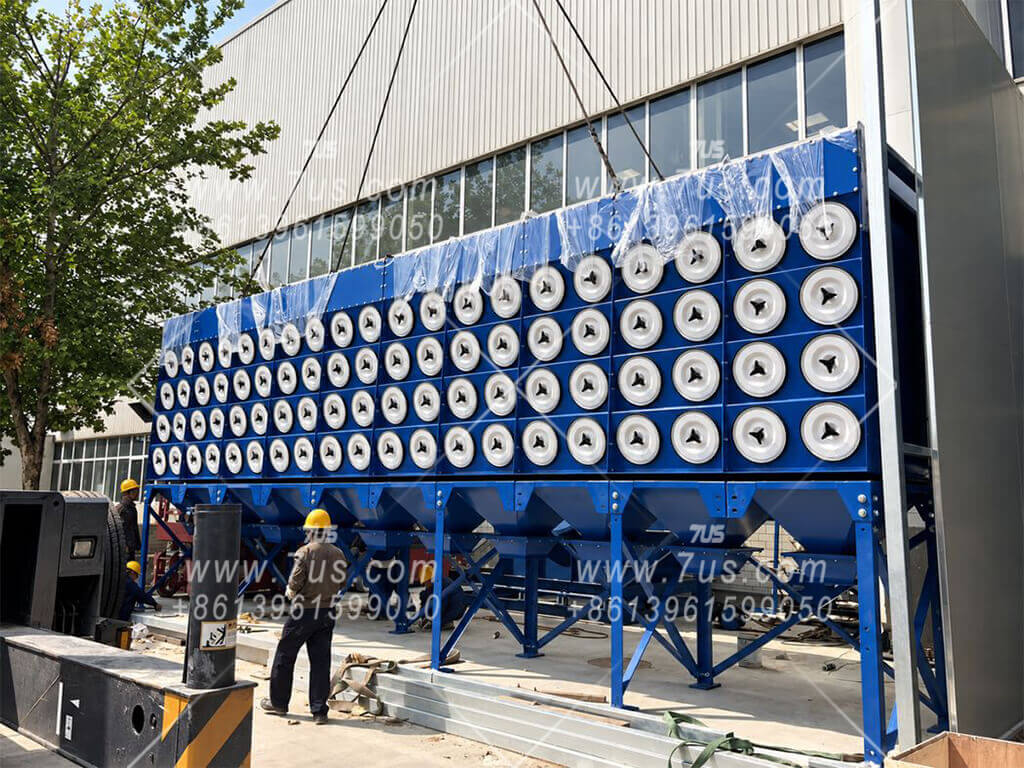
EHCDP modular downflow dust collectors with horizontal side-insertion cartridges, automatic pulse-jet cleaning and 2-, 3-, 4- or 5-level module configurations.

  • Horizontal cartridges with side access
  • Automatic pulse-jet cleaning
  • 2 / 3 / 4 / 5-level modular configurations
  • Fan, discharge & HEPA options
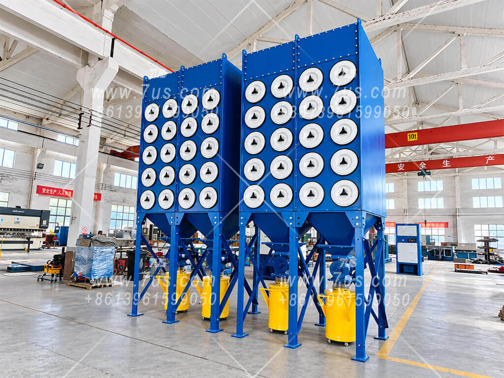
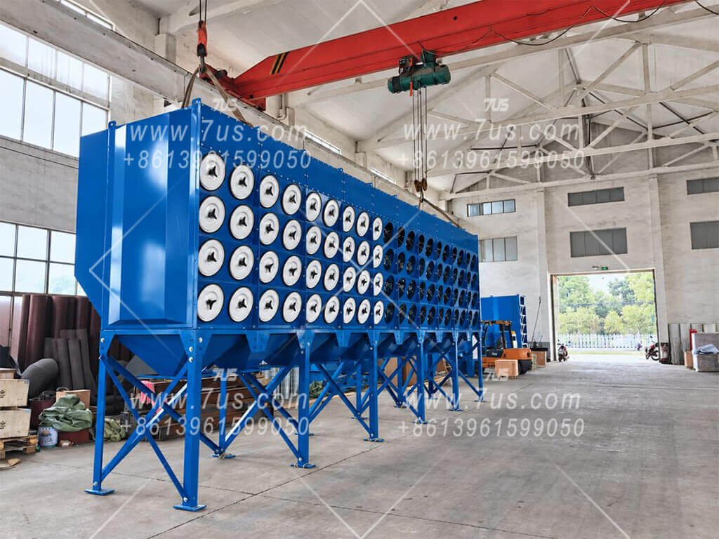
EHCDP horizontal cartridge dust collector front view
Open/Open CartridgeØ352 × 660 mm typical size
Pulse-Jet CleaningAutomatic filter cleaning
Modular ConstructionEasy capacity expansion
OEM AvailableRAL color / private label options
01Configurations
Contents ↑

Horizontal Cartridges. Modular Construction.

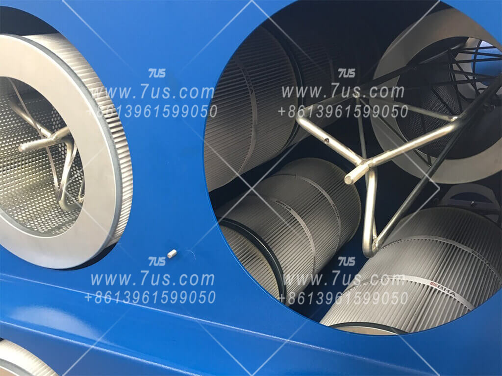
EHCDP combines horizontal side-insertion cartridges with bolted collector modules. Choose a 2-, 3-, 4- or 5-level configuration, then combine compatible modules to suit the required filter area and installation space.

01

Horizontal Cartridge Arrangement

Horizontally mounted cartridges are accessed from the service side. Allow sufficient side clearance for cartridge removal and routine maintenance.

02

Modular Units

Standard collector modules can operate individually or be combined to increase filtration area and airflow capacity for larger systems.

02How It Works
Contents ↑
HOW IT WORKS

Downflow Filtration & Pulse Cleaning

Dust-laden air passes through the horizontal cartridge section, where dust is captured on the outer filter surfaces. Cleaned air exits through the clean-air side. Reverse pulse cleaning releases the dust cake so it can fall into the dust collection section.

EHCDP HORIZONTAL CONFIGURATION

Horizontal Cartridge Arrangement
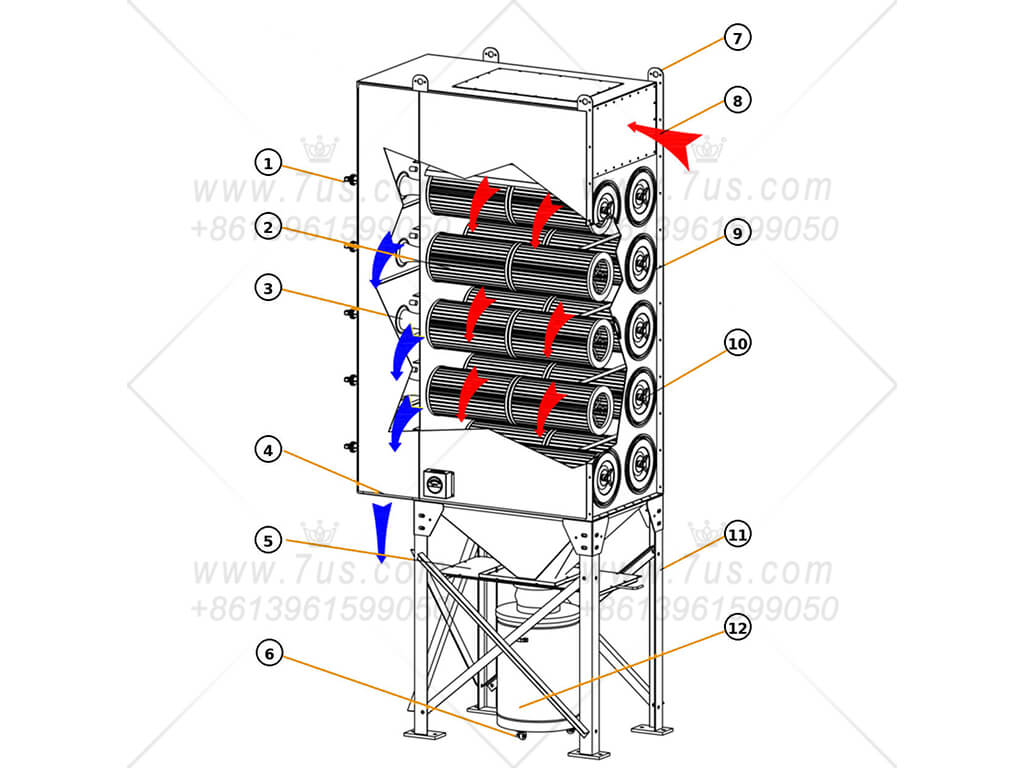
Horizontal cartridge dust collector airflow diagram with numbered components

Horizontal cartridges provide side access for maintenance. Pulse cleaning and filter-media selection should be matched to the dust characteristics and loading.

03Cartridge Sealing
Contents ↑
SEALING DESIGN & MANUFACTURING PRECISION

Cartridge Sealing Reflects Manufacturing Accuracy

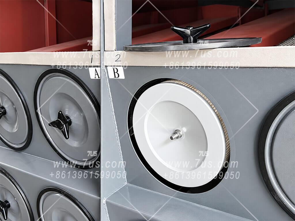
Both arrangements use two cartridges installed in series on the same support frame. The visible difference is how sealing pressure is achieved — and that difference is closely related to dimensional control, cartridge alignment, cover-plate fit and consistent gasket compression.
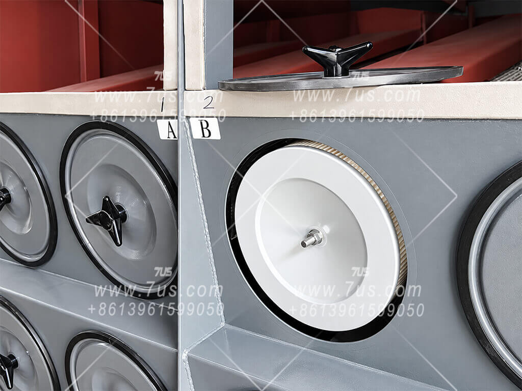
REFERENCE ARRANGEMENT

Additional Internal Center Nut Required

Open-open plus open-closed cartridge pair with center-nut sealing
01Cover Plate + Gasket + Internal Center Nut

Two cartridges are installed in series on the same support frame. The cover plate, gasket, center rod and external three-lobe handle are all present, while an additional internal center nut is also used to provide cartridge clamping. During cartridge replacement, this internal nut must be removed and re-tightened before the cover is secured again.
7US STANDARD DESIGN

Precision Cover-Plate & Gasket Sealing

7US open-open cartridge pair sealed by cover plate and gasket without center nut
02No Internal Center Nut Required

Two open/open cartridges are installed in series on the same support frame. Precise cartridge positioning, support-frame alignment and controlled gasket compression allow the cover plate to provide the required sealing pressure without an internal center nut. The center rod remains in place for the external three-lobe handle that locks the cover plate, while routine cartridge replacement avoids the extra internal nut-removal and re-tightening operation.

Reliable sealing starts with manufacturing accuracy — not with adding more fasteners.
Both designs use two cartridges in series, but the 7US arrangement achieves sealing through precise cartridge positioning, support-frame alignment, cover-plate fit and controlled gasket compression, so no additional internal center nut is required. For experienced dust-collection professionals, the cartridge sealing structure is one visible indicator of manufacturing precision and assembly quality.
04Modular Construction
Contents ↑
MODULAR CONSTRUCTION

What Makes a Collector Truly Modular

A segmented front appearance does not always mean a true modular cartridge dust collector. The real difference is at the connection interface: whether each section is fabricated as an independent structural module and then mechanically joined to the next module.

WHY MODULAR?

Control Welding Distortion Before Controlling the Whole Collector

ONE LARGE FULLY WELDED CABINET

Cumulative distortion becomes harder to control as the collector gets larger.

A very large continuous enclosure requires more welding across a longer structure. As weld length and heat input increase, shrinkage and dimensional drift can accumulate across the cabinet, making final alignment more difficult to control.

More weld length→More heat input→Harder cumulative control
→
7US INDEPENDENT MODULES

Each module is fully welded and dimensionally controlled before final assembly.

7US divides a large collector into repeatable structural modules. Each module is welded in dedicated fixtures, checked as an individual unit, and only then sealed and bolted to adjoining modules. This keeps welding distortion localized and helps reduce cumulative dimensional error across a large collector.
Fixture welding→Module inspection→Controlled final fit-up
Modular construction is therefore a manufacturing-control strategy, not only a transport or installation feature. Smaller repeatable welding units are easier to fixture, inspect and keep dimensionally consistent before they are combined into a large collector.
REFERENCE CONSTRUCTION

Integrated Cabinet with Modular Appearance

Visual division does not necessarily create an independent structural module.
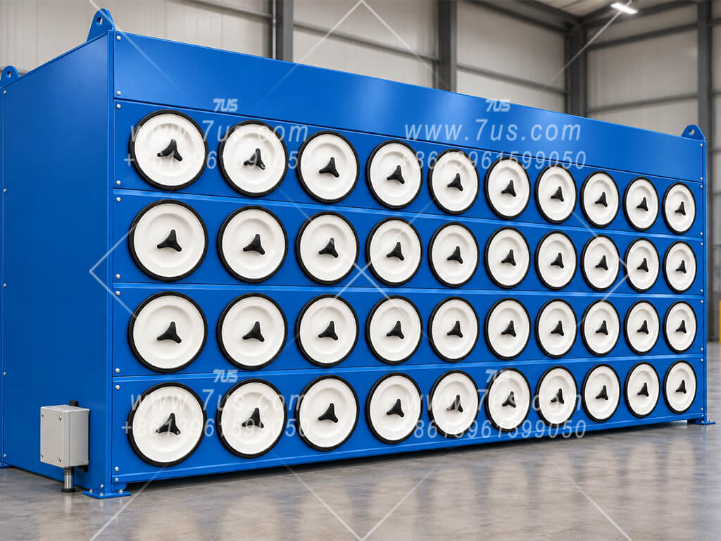
Integrated cabinet with a visible divider or reinforcement strip
Visual divider / reinforcement on a continuous cabinet
Continuous cabinet with repeated cartridge rows and no true module joint
Repeated cartridge layout without a true structural module joint

These layouts can create a modular-looking front face while the main enclosure remains largely continuous. A divider, reinforcement strip or repeated cartridge pattern does not by itself prove that two independently fabricated modules have been structurally joined.
Continuous or largely integrated cabinet body
Visual divider or reinforcement may create a segmented appearance
No clear independent module-to-module bolted interface
7US STANDARD CONSTRUCTION

True Bolted Modular Construction

Independent structural modules with real mating surfaces and mechanical fastening.
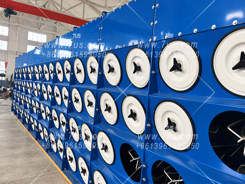
7US independent dust collector modules assembled side by side
Real module boundaries and bolted joints on a 7US collector
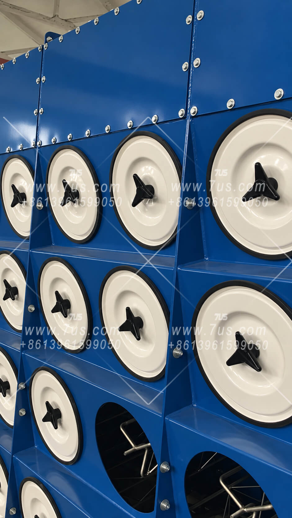
Close-up of 7US vertical module seam and fastening
Independent side plates form the structural connection zone
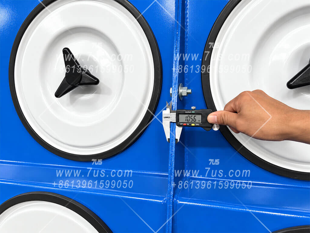
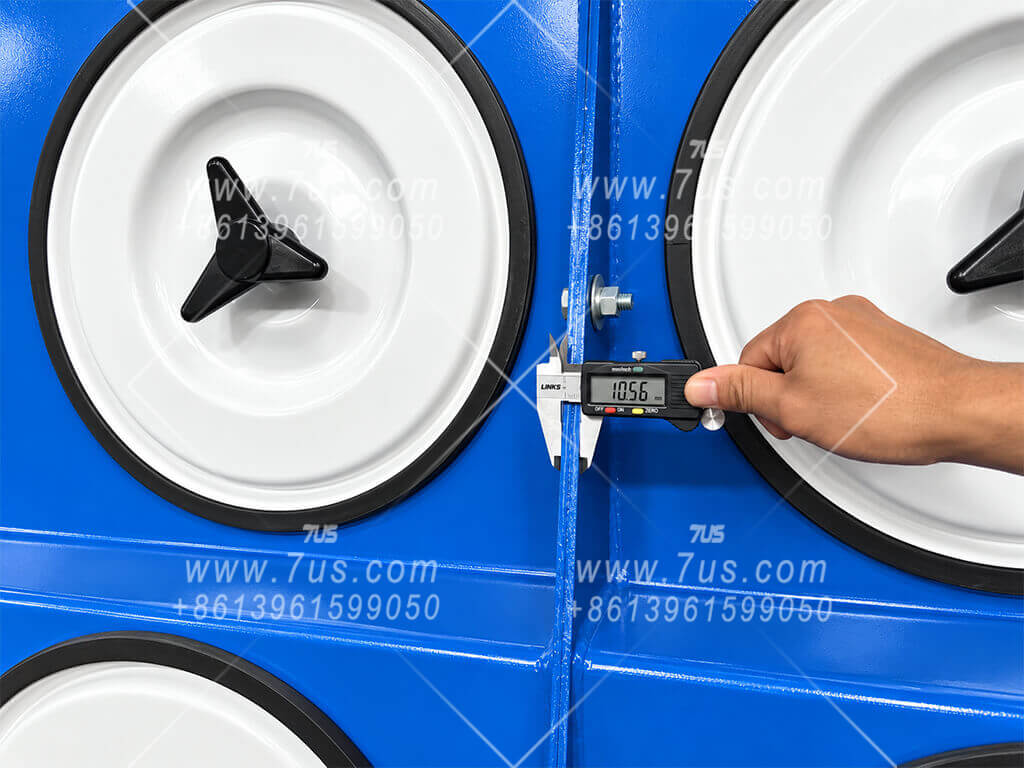
Caliper measurement at the assembled 7US module joint
Assembled module joint — directly measured

Each 7US module is fabricated as an independent structural unit with its own side plate. Before adjacent modules are bolted together, industrial structural sealant is applied continuously between the mating surfaces to create an air-tight interface. Bolts and nuts then provide the mechanical clamping force, forming a genuine sealed module-to-module structural joint.

Independent module side plates
Structural sealant applied between mating surfaces
Bolts and nuts provide mechanical clamping
Air-tight structural joint between modules
Sealed first, bolted second. The visible joint is structural — not decorative.
A true modular collector must address both structural strength and air-tightness. 7US modules are manufactured separately. During assembly, structural sealant is applied to the mating surfaces first to seal the interface; bolts and nuts are then tightened to provide the mechanical connection and clamping force. The modular concept therefore continues from factory fabrication through transport and final assembly.
05Manufacturing & Installation
Contents ↑
BUILT FOR ACCURACY

Manufacturing Details You Can See

A complete manufacturing process matters, but the details that affect fit, sealing and repeatability are easier to judge from real production evidence. The photographs below show how 7US controls fabrication, positioning, assembly and module fit-up in actual production.

01Laser Cutting
02CNC Bending
03Fixture Welding
04Trial Assembly
05Surface Preparation
06Powder Coating
07Final Assembly

Proof of Precision

Instead of relying only on specification text, these details show the actual fixtures, measurements, components and assembled modules used in production.
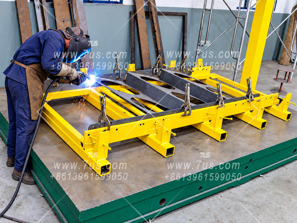
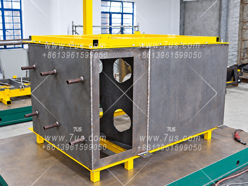
01

Fixture-Controlled Fabrication

Critical geometry is held during welding and checked again during trial assembly.
Welding fixture used for 7US cartridge dust collector cabinet fabrication
Dedicated welding fixture
Positioning and clamping detail during dust collector cabinet fabrication
Positioning & clamping detail
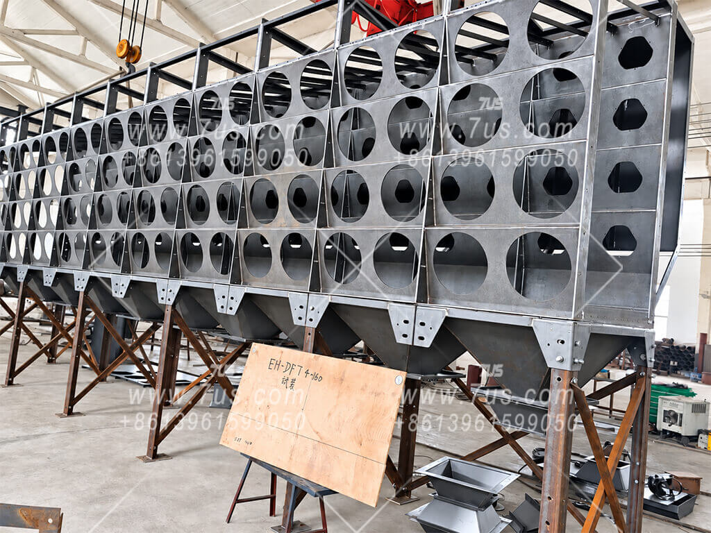
Uncoated modular cabinet trial assembly
Trial assembly before coating
What customers can verify: the cabinet is not assembled only by visual alignment. Fixtures and pre-assembly are used to control repeatability before finishing.
02

Measured Construction Details

Real production measurements, hardware and grounding details are shown directly.
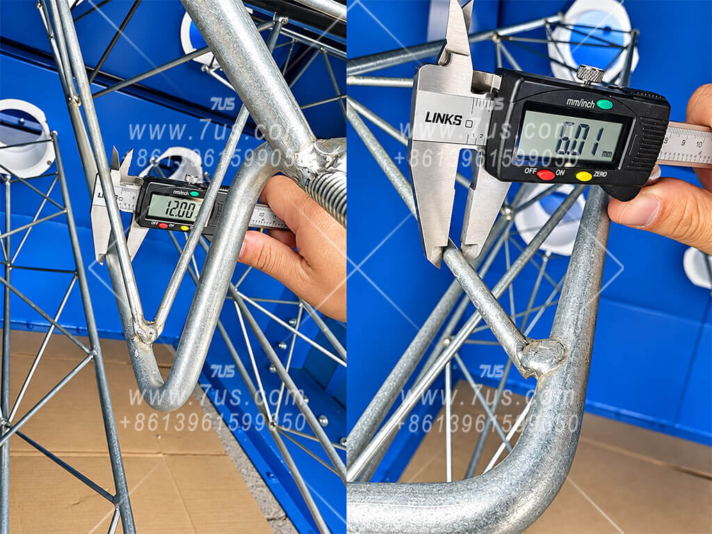
Filter support frame measurement
Filter-support frame members
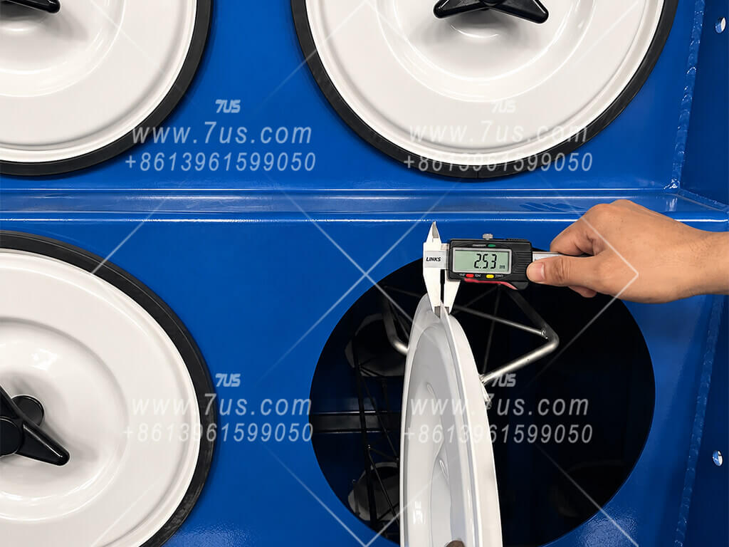
Cover plate thickness measurement
Cover-plate thickness check
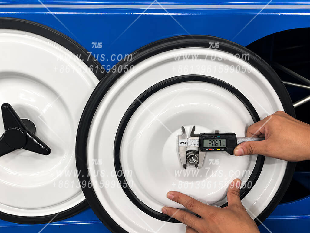
Three-lobe handle and threaded insert detail
Three-lobe handle & threaded insert
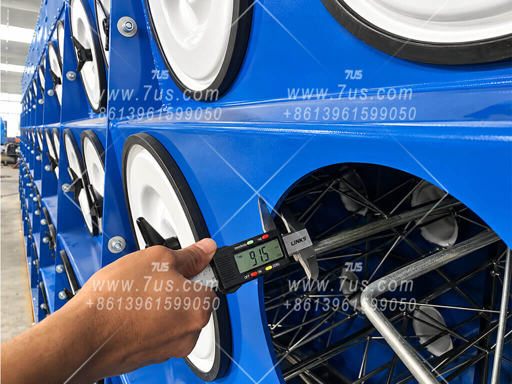
Curved plate thickness measurement
Curved structural plate
Module joint measurement
Module-joint build-up
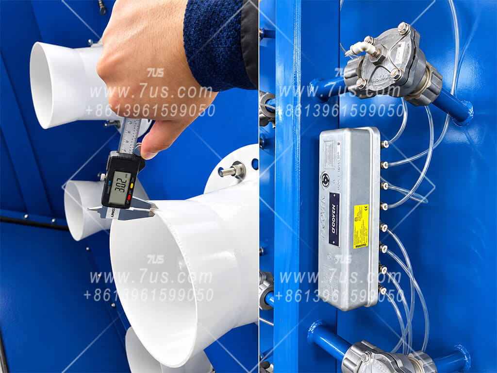
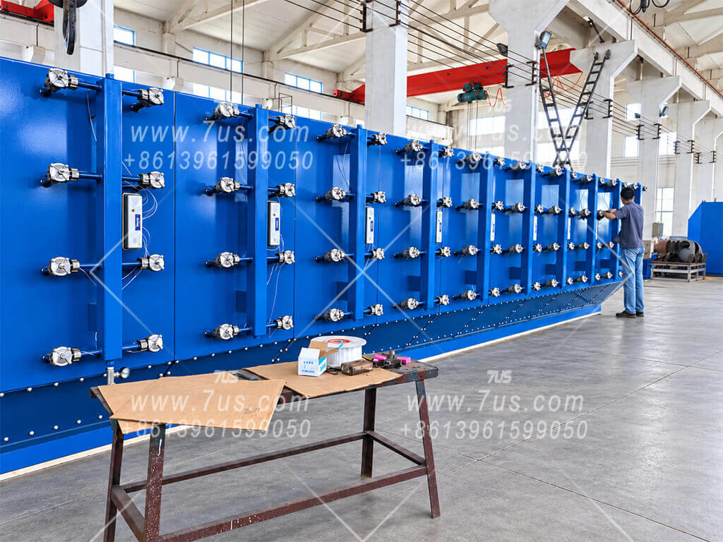
Venturi and pulse cleaning components
Venturi & pulse-cleaning hardware
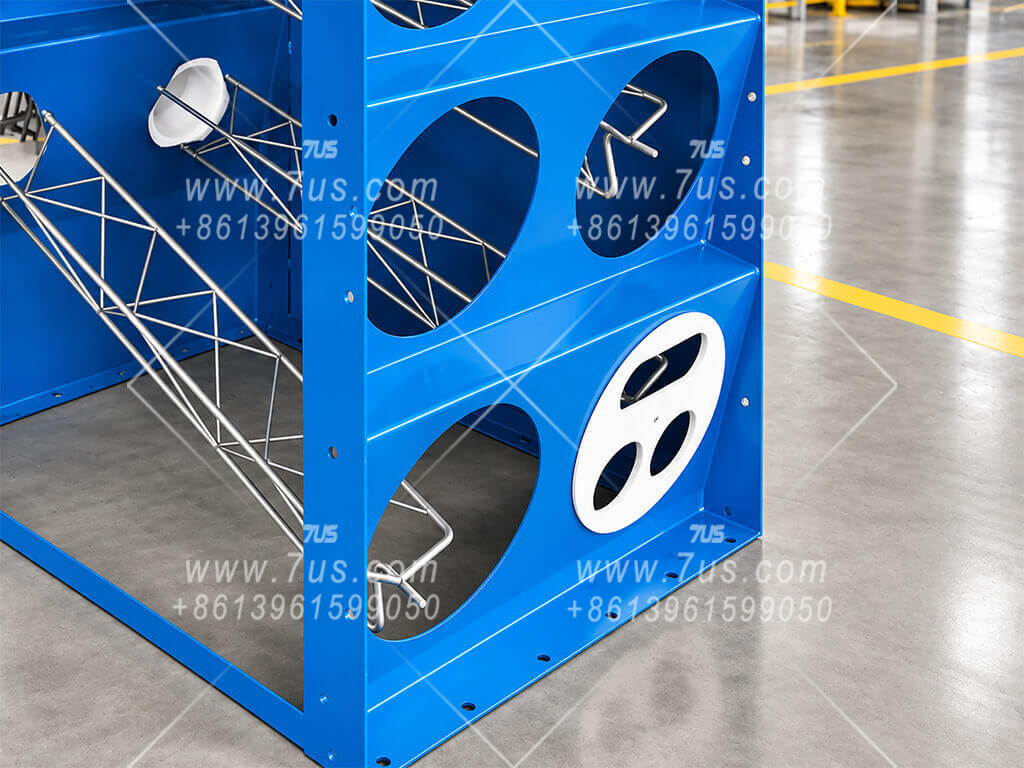
White positioning jig for filter support installation
Positioning jig for support installation
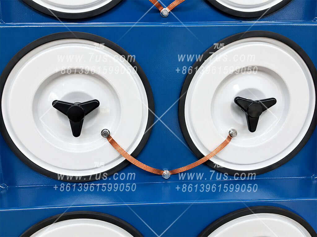
Copper grounding braid for static charge dissipation on the cartridge cover
Anti-static grounding braid
Eye-level evidence, not marketing claims: material thickness, frame construction, fastening, static-grounding and positioning methods can be inspected directly from production photographs.
03

Installation-Ready Duct Interfaces

Removable inlet / outlet flange templates simplify matching ductwork fabrication.
Removable collector flange template
→Use as
fabrication pattern
Matching duct flange — same opening & bolt pattern
DESIGNED FOR EASIER INSTALLATION

Remove the Template. Build the Matching Flange.

7US inlet and outlet connections can be supplied with removable flange template plates. The template reproduces the actual collector opening size and bolt-hole pattern, so the duct fabricator can use the removed plate directly as the reference for the mating duct flange. This avoids repeated site measurement, redrawing and bolt-hole guesswork.
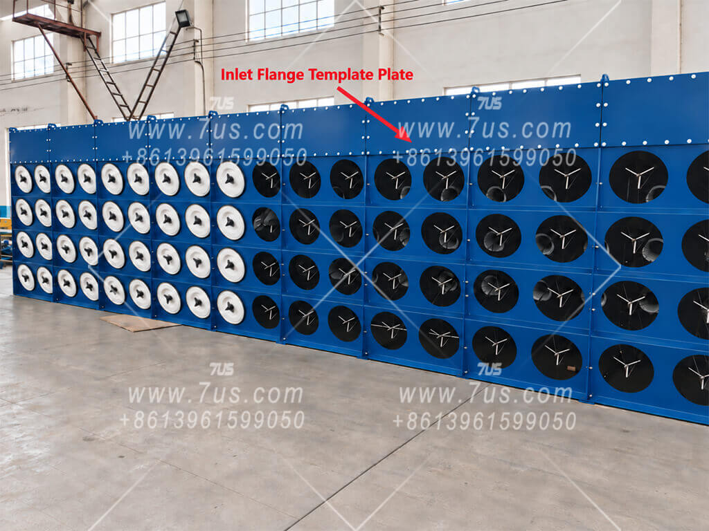
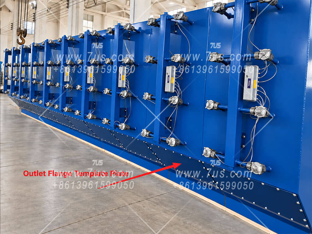
Exact Opening Size The duct flange follows the actual collector interface dimensions.
Exact Bolt Pattern Bolt-hole positions can be transferred directly from the template.
Faster Field Fit-Up Less measuring and fewer alignment surprises during duct connection.
A small manufacturing detail that can save significant installation time. The same concept can be used at both inlet and outlet interfaces.
Actual 7US dust collector showing removable inlet flange template plate
Inlet InterfaceFull-size removable flange template plate used as the duct fabrication pattern.
Actual 7US dust collector showing removable outlet flange template plate
Outlet InterfaceThe same removable-template concept applied to the clean-air outlet connection.
04

Independent Modular Construction

Upper and lower sections are fabricated separately, then assembled into one complete modular collector.
Front view of multiple assembled modules
Multiple modules — front view
Powder-coated parts prepared for assembly
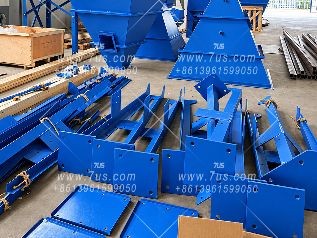
1 · Powder-coated parts ready for assembly
Upper housing section prepared as a separate assembly
2 · Upper housing section
Lower housing section prepared as a separate assembly
3 · Lower housing section
Complete collector after upper and lower sections are assembled together
4 · Complete unit after upper/lower assembly
The modular structure is visible through the assembly sequence. Powder-coated parts are prepared first; the upper housing and lower housing sections are built as separate assemblies, then aligned and bolted together to form the complete collector.
05

From Factory Trial Assembly to Site Installation

The same modular concept continues through inspection, transport and final erection.
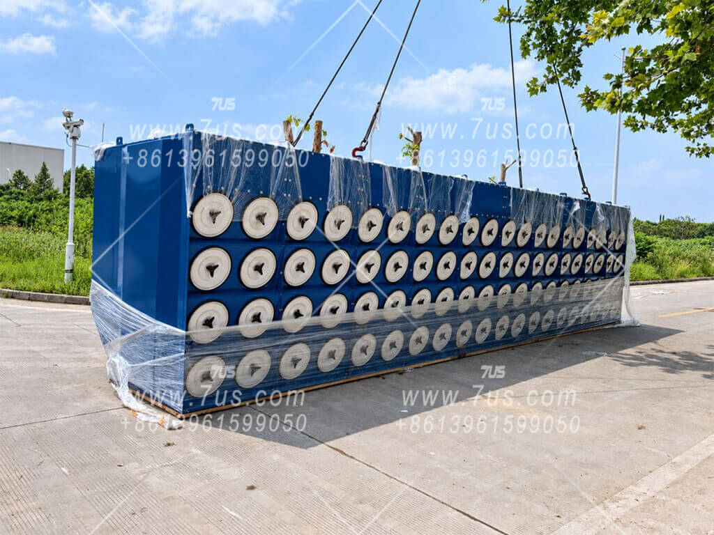
Factory trial assembly
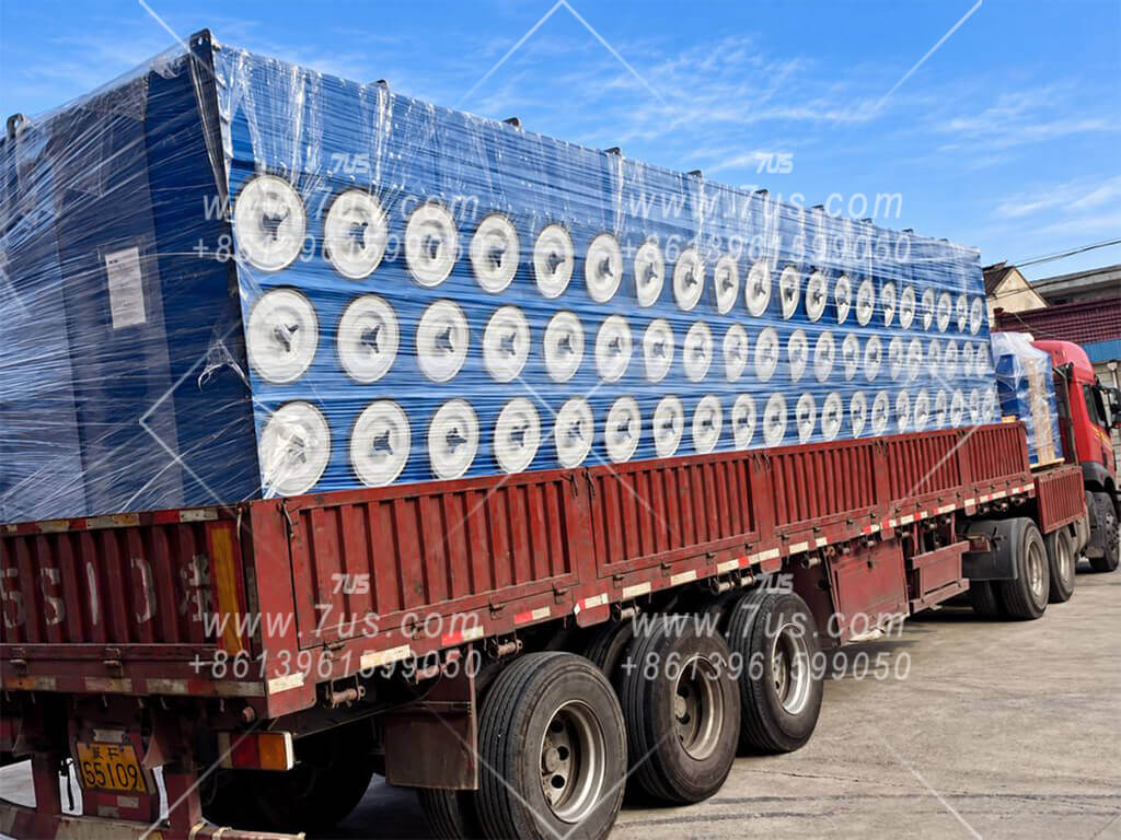
Large modular collector loaded for transport
Modular transport
Upper collector casing arrived at site
Upper casing at site
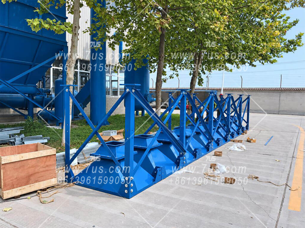
Lower collector structure at installation site
Lower structure positioned
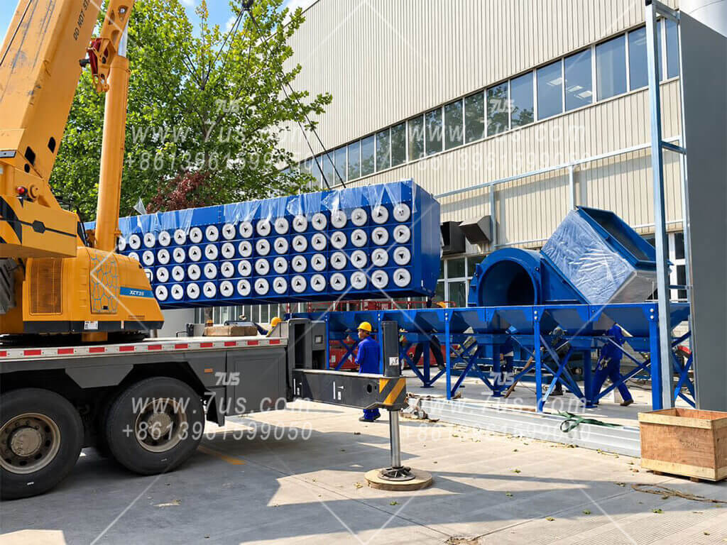
Crane assembling upper and lower collector modules
Crane-assisted assembly
Completed modular dust collector installation
Completed installation

Manufacturing Quality Should Be Visible

The goal of this section is not to claim quality with adjectives. It is to show the fixtures, measurements, construction details, trial assembly and finished installation so experienced buyers can judge the manufacturing standard for themselves.

Full process capability: laser cutting, CNC bending, welding, surface preparation and powder coating remain part of the complete process — but the details above are where manufacturing discipline becomes visible.

06 EHCDP Model Selection
Contents ↑
HORIZONTAL CARTRIDGE ARRANGEMENT

How to Select an EHCDP Horizontal Collector

EHCDP modules are available with 2, 3, 4 or 5 filter levels. Select the filter media and required filtration area, then choose the module arrangement to fit the available height, width and maintenance access.

Shared modular platform: cartridge sealing, bolted module joints, removable duct-interface templates and manufacturing controls described in Chapters 03–05 also apply to EHCDP. Photographs in those chapters illustrate shared construction and manufacturing details; EHCDP product views are shown in Chapter 08.
CARTRIDGE ORIENTATION Horizontal Side Insertion Cartridges remain level and are accessed from the service side.
STANDARD CARTRIDGE Ø352 × 660 mm Typical outside cartridge size for the EHCDP family.
ADDITIONAL HEIGHT OPTION 2 / 3 / 4 / 5 Levels The 5-level arrangement increases cartridge quantity without adding another module across the floor width.
CAPACITY EXPANSION Modular Combination Base modules can be combined side by side according to required filter area and site layout.
FINE FUME / LOWER PARTICULATE LOADING

Paper / Cellulose Media

≈20 m²per cartridge

Because paper / cellulose media can be pleated more densely within the same outside cartridge size, a larger effective filter area can be achieved in the same volume. The denser pleat arrangement, however, also increases airflow resistance, so the recommended design filtration velocity is lower than for polyester media. This configuration is well suited to welding fumes and similar fine-fume duties.

  • Same outside size as the polyester option
  • Larger effective filter area
  • Can reduce module quantity for suitable fume duties
  • Recommended design filtration velocity: generally ≤0.8 m/min
HIGHER PARTICULATE LOADING

Polyester Media

≈10 m²per cartridge

Wider pleat spacing is better suited to grinding dust and higher particulate loading, where dense pleats can make pulse-cleaning and dust shedding more difficult.

  • Same outside size as the paper / cellulose option
  • More open pleat spacing for particulate release
  • Preferred for grinding and higher dust-loading duties
  • Recommended design filtration velocity: generally ≤1.1 m/min

EHCDP Standard Module Selection

The model code identifies the filter levels and total cartridge quantity. Final airflow is confirmed from filter media, total effective filter area and the design filtration velocity for the actual dust — not from cartridge quantity alone.

Model Filter Levels Cartridges Cartridge Size Paper / Cellulose Area* Polyester Area* Arrangement
EHCDP2-424Ø352 × 660 mm≈ 80 m²≈ 40 m²Compact-width module
EHCDP2-828Ø352 × 660 mm≈ 160 m²≈ 80 m²Standard-width module
EHCDP3-636Ø352 × 660 mm≈ 120 m²≈ 60 m²Compact-width module
EHCDP3-12312Ø352 × 660 mm≈ 240 m²≈ 120 m²Standard-width module
EHCDP3-18318Ø352 × 660 mm≈ 360 m²≈ 180 m²Extended-width module
EHCDP4-16416Ø352 × 660 mm≈ 320 m²≈ 160 m²Standard-width module
EHCDP4-24424Ø352 × 660 mm≈ 480 m²≈ 240 m²Extended-width module
EHCDP5-20 5 Level520Ø352 × 660 mm≈ 400 m²≈ 200 m²Standard-width / taller module
EHCDP5-30 5 Level530Ø352 × 660 mm≈ 600 m²≈ 300 m²Extended-width / taller module
SELECTION PRINCIPLE Airflow = Total Filter Area × Design Filtration Velocity × 60

A model number describes the module geometry. The acceptable airflow depends on dust loading, filter media and the design filtration velocity selected for the application.

TYPICAL AREA FOR PRELIMINARY SELECTION

Cartridges with the same outside dimensions can have different effective filtration areas because the pleat construction is different.

≈20 m² / cartridgePaper / cellulose media
≈10 m² / cartridgePolyester media

Example: EHCDP3-12 Modular Scaling

One 3-level base module can be repeated horizontally. The same modular principle also applies to compatible 2-, 4- and 5-level families.

EHCDP3-121 module · 12 cartridges
EHCDP3-242 modules · 24 cartridges
EHCDP3-363 modules · 36 cartridges
EHCDP3-484 modules · 48 cartridges
EHCDP3-605 modules · 60 cartridges
* Filter areas use approximately 20 m² per paper / cellulose cartridge and 10 m² per polyester cartridge for preliminary selection. Final cartridge construction, media specification, dimensions and project airflow are confirmed before order.
07 System Options
Contents ↑
CONFIGURE THE COLLECTOR AROUND THE PROJECT

Available System Options

The downflow cartridge dust collector body can be configured around the actual dust load, discharge method, electrical standard, safety requirements and final filtration target. The options below can be selected individually or combined as part of a project-specific system configuration.

01 · FILTER CARTRIDGES

Filter Media Options

Select the basic media first, then add surface or safety functions according to the dust.

  • Cellulose / paper filter cartridges
  • Polyester filter cartridges
  • PTFE membrane optional
  • Flame-retardant option
  • Antistatic option
02 · MATERIAL & CONSTRUCTION

Collector Material & Structural Customization

The collector body can be manufactured in different materials and structural specifications to suit corrosion conditions, process requirements and customer standards.

  • Q235 carbon steel
  • SS304 stainless steel
  • SS316L stainless steel
  • Customer-specified coating color
  • Plate thickness can be customized for special service conditions
  • Reinforcement and structural strengthening can be customized as required
03 · HOPPER CONFIGURATIONS

Independent or Boat-Type Hopper

Independent Hopper
  • Low-profile hopper for lower dust loading
  • High-capacity hopper for higher dust loading
Boat-Type Hopper
  • One common large hopper can serve multiple collector modules
04 · DUST DISCHARGE

Discharge Valve & Screw Conveyor

  • Manual slide gate
  • Manual butterfly valve
  • Motorized rotary airlock valve
  • Screw conveyor available for multi-module collectors
05 · PULSE CLEANING

Pulse-Jet Cleaning System

  • Pneumatic pilot-operated valves + centralized solenoid valve box
  • Integrated solenoid-operated pulse valves
  • Pulse interval and duration adjustable by pulse controller or PLC
  • Valve and control component brands can be specified
06 · FAN & ELECTRICAL CONTROL

Fan, Motor & Control Cabinet

Fan / Motor
  • Fan brand and motor brand can be specified
  • Voltage and 50 / 60 Hz frequency configured for the destination
Electrical Control
  • Electrical component brand can be specified
  • PLC optional
  • HMI / touchscreen optional
  • VFD optional
07 · SAFETY & ACCESS

Explosion Protection, Safety & Maintenance

  • Explosion vent panel
  • Flameless explosion venting device
  • Explosion-proof motor
  • Explosion-proof electrical cabinet
  • Spark arrestor / spark trap
  • Maintenance platform available as required
INTEGRATED TWO-STAGE FILTRATION

Integrated Cartridge + HEPA Dust Collector Module

7US can integrate primary cartridge filtration and secondary HEPA filtration into one modular collector body. The cartridge section and HEPA section are arranged vertically within the same structural module, creating a compact two-stage filtration unit rather than two separate machines connected by ductwork.

Cartridge + HEPA in One Cabinet
Vertically Integrated Two-Stage Filtration
No Separate HEPA Unit Required
One integrated module, engineered as one filtration system. The integrated arrangement reduces external duct connections and installation space. HEPA filter area, final pressure drop and fan selection are engineered together with the primary cartridge stage to maintain the required system airflow and final filtration performance.
Explosion-protection items are configurable components for project requirements. Final compliance scope and component certification should be confirmed for the destination market and application.
08 Applications & Delivery
Contents ↑
APPLICATION RANGE & PROJECT DELIVERY

Typical Applications & Product Views

Industrial cartridge dust collectors can be configured for a wide range of dry-dust and fume applications. Application suitability is determined by the actual dust characteristics, loading, filtration media, airflow and safety requirements — not by equipment appearance alone.

TYPICAL APPLICATIONS

Common Industrial Dust & Fume Duties

EHCDP modular collectors can be engineered for different process conditions after the dust source and operating requirements are confirmed.

Shot & Sand Blasting Grinding & Polishing Welding Fume Laser Cutting Metalworking Powder Handling Woodworking Foundry & Dry Process Dust
PROJECT DELIVERY

From Factory Preparation to Site Assembly

Large collectors are prepared as modular equipment for inspection, transport and practical field assembly. Site installation is normally completed by the customer or local contractor with drawings and technical guidance from 7US.

01 Factory Trial Assembly Fit and interfaces checked before shipment.
02 Modular Packing Sections prepared for practical transport.
03 Shipment Module dimensions coordinated with logistics.
04 Assembly Guidance Drawings and remote technical support available.

EHCDP Product Views

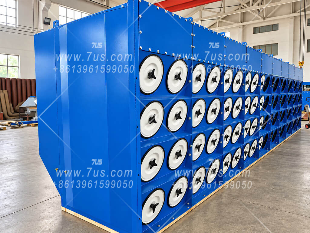
Front and rear views of the EHCDP horizontal-cartridge modular collector show the service side and rear-side structure of the same equipment.
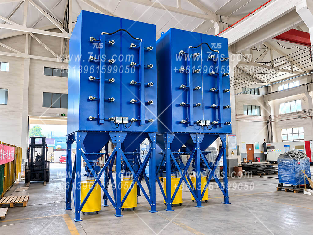
EHCDP horizontal cartridge dust collector front view
Front ViewActual EHCDP horizontal-cartridge modular collector.
EHCDP horizontal cartridge dust collector rear view
Rear ViewRear-side structure of the same horizontal-cartridge platform.
More application references and project photographs are available on request.
09 Project Inquiry
Contents ↑
PROJECT CONFIGURATION

Configure Your EHCDP System

The collector body can be supplied separately, or configured with a fan and controls for the confirmed airflow, system pressure and power supply.

Equipment Supply

Material, coating color, discharge arrangement and HEPA options can be selected for the project. See the system options above for available configurations.

Drawings & Assembly Support

Detailed GA / DWG project drawings can be prepared after the configuration, interfaces and order requirements are confirmed. Site assembly is carried out by the customer or local contractor with drawings and remote technical guidance from 7US.

Preparing the public shell…