
7US 7US Industrial dust collector since 1994
INLINE SWIRL SEPARATION

Centrifugal
Spark Arrestors

Help reduce the sparks and hot particles reaching your dust collector. Suitable for sparks carried in ambient-temperature air from welding, laser cutting and grinding, as well as sparks and embers in high-temperature flue gas from biomass boilers and smelting furnaces. Installed in the inlet duct upstream of the dust collector.

Configured for your processFor selection, provide the duct outside diameter, operating temperature and composition of the spark-bearing material.
WeldingLaser cuttingGrindingBiomass boilersSmelting furnaces

Manufactured by Jiangsu Erhuan Environmental Technology Co., Ltd. under the 7US brand. Also known as centrifugal spark arresters, swirl-type spark traps or spark catchers.

WELDING FUME EXTRACTIONInstalled upstream of the dust collector. This welding application uses a collection bucket without a rotary airlock valve.
Inline installationIn the inlet duct before the dust collector
Process-based sizingDuct diameter, temperature and material
High-temperature finishHeat-resistant coating selected for the operating temperature
Motorized rotary airlockOptional configuration for high-dust-load flue gas from biomass boilers and smelting furnaces

Looking for a spark eliminator for your dust collection system? These units help reduce metal sparks and glowing embers reaching downstream filters. Configuration depends on the process, temperature and material; complete elimination of ignition sources is not guaranteed.

01

How swirl separation works

A hemispherical inlet guide distributes the flow into fixed vane passages. The front and rear housings work together to promote spark cooling and particle separation.

INSIDE THE SPARK ARRESTORThe protruding hemispherical guide distributes incoming gas into the surrounding vane passages. Vane count and angle are configured to suit the unit diameter.
1

Distribute the incoming gas

The protruding hemispherical guide at the inlet directs the incoming spark-bearing gas outward, distributing it around the inlet and into the flow passages formed by the surrounding stationary vanes.

2

Accelerate and redirect in the front housing

The vane passages accelerate the gas and impart a swirling motion. Sparks and entrained particles collide with internal surfaces, promoting heat transfer, cooling and spark extinguishment. Vane count and angle are matched to the unit diameter.

3

Continue separation in the rear housing

The rear housing contains no guide vanes. The gas continues to swirl, carrying sparks and heavier particles along the inner wall for further contact and separation. Separated material moves toward the lower discharge opening, while the gas leaves through the outlet toward the dust collector.

4

Remove the separated material

Welding applications can use a collection bucket. For biomass boiler and smelting furnace duties with high dust loading, a motorized rotary airlock transfers collected material through its rotor pockets to the discharge pipe and bin, helping maintain discharge while limiting air ingress into the negative-pressure system.

Pre-treatment before filtration. Fine dust and fume continue to the downstream dust collector. Spark reduction depends on the process and operating conditions; complete elimination of ignition sources is not guaranteed.
FLOW & DISCHARGE
Front and rear housing flow schematicIncoming gas is distributed by a hemispherical guide into fixed vane passages in the front housing. Swirling flow continues in the rear housing without vanes. Separated particles leave through the lower discharge; gas flows to the dust collector. FRONT HOUSINGREAR HOUSINGFixed vane passagesNo guide vanes Spark-bearing gas To dust collector Hemispherical inlet guide Separated material

Conceptual section: flow paths and internal features are simplified, not to scale. Discharge equipment is selected for the application.

02

Duct connections & parallel arrangements

Provide your duct outside diameter. Matching flange pairs are supplied as standard, and oversized installations can be divided into smaller units in parallel.

MATCH YOUR EXISTING DUCT

Only the duct outside diameter is needed for connection sizing

For connection sizing, simply provide the accurate outside diameter of your duct. We make the inlet and outlet connections to match, including non-standard sizes.

INLETØ500 mm
OUTLETØ500 mm

Example connection size. Other diameters can be made to order.

Non-standard sizes
For example, a duct with a 535 mm outside diameter can be matched with corresponding inlet and outlet connections.
Flange pairs included
Every spark arrestor is supplied with mating flange pairs at the inlet and outlet, including the matching flanges for welding to your ductwork.
No bolt-hole measurements
You do not need to measure or supply flange dimensions, bolt-hole spacing or a drilling drawing.
SMALLER UNITS IN PARALLEL

Split oversized units for transport

A single spark arrestor for a DN3000 duct would be too large for conventional transport. The main duct can instead divide into smaller parallel branches and merge again downstream.

DN3000 main duct2 × DN2200 or 4 × DN1500 in parallel
4 × DN1500
The combined nominal cross-sectional area equals that of one DN3000 duct.
2 × DN2200
An approximate area-matched alternative, with about 7.6% more combined nominal cross-sectional area than one DN3000 duct.
Project layout
Area matching provides a starting point. Branch layout, flow distribution, overall equipment dimensions and shipping arrangements are confirmed for the project.

Independent structural supports are required

Larger-diameter spark arrestors are heavier. Each unit must have its own adequately designed support frame or structural supports to carry its weight. Never suspend the spark arrestor from the ductwork or rely on the connecting ducts and flanges to support it. Unsupported equipment can overload the ductwork, cause connection failure and create a serious falling-equipment hazard.

DN1200 — General arrangement

Example dimensions and connection layout. Click to enlarge.

DN1500 — General arrangement

Example dimensions and connection layout. Click to enlarge.

Reference drawings for two example sizes. Final dimensions, supports and discharge arrangements are confirmed for each project.

STEEL PLANT CASE STUDY

Two DN2200 spark arrestors in parallel

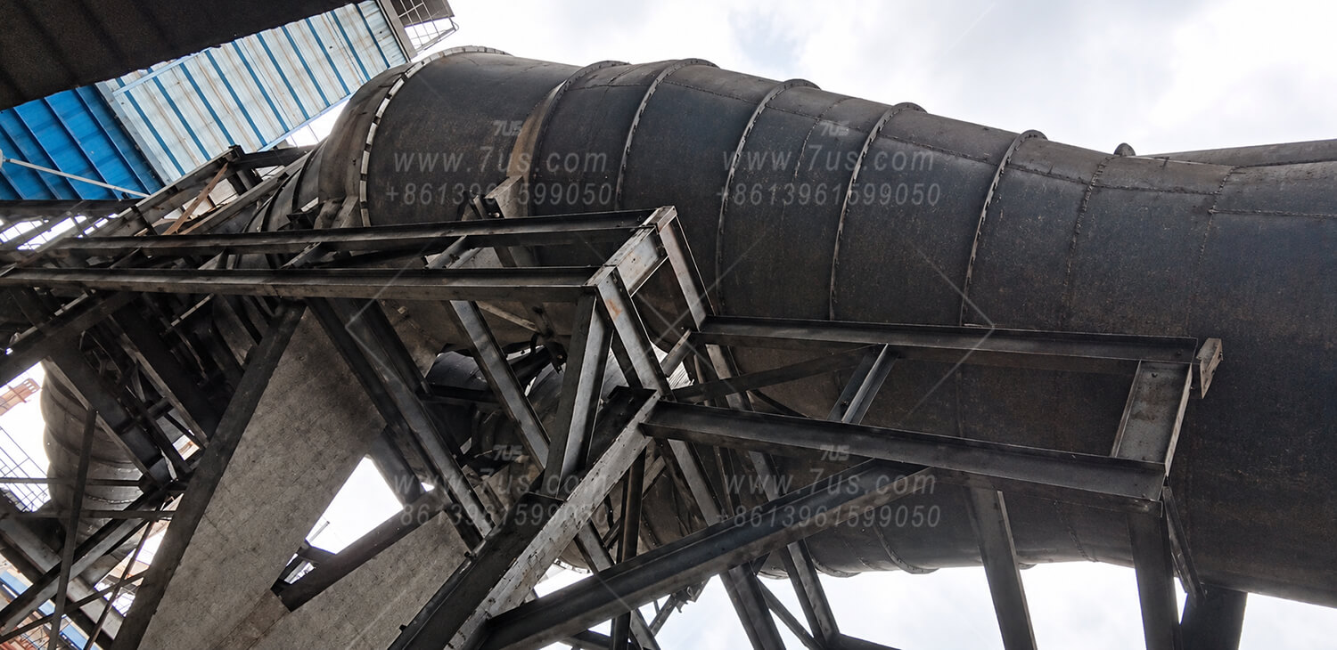
For this steel plant project, a Ø3000 mm main duct was divided into two branches, each fitted with a DN2200 centrifugal spark arrestor. This parallel arrangement avoided transporting one oversized unit. The combined nominal cross-sectional area is approximately 7.6% larger than that of the Ø3000 mm main duct, providing an approximate area match.

Steel plant installation with two DN2200 spark arrestors connected in parallel to a 3000 mm main duct
Actual installation — parallel duct arrangementThe wide view shows the two branches and the installed spark arrestors.
Actual installation — another viewA second view of the equipment and its supporting structure.
Design illustration — twin unitsFront view showing the internal guide vanes and lower collection areas.

Shared or separate dust discharge: The two spark arrestors shown share one dust discharge pipe and one rotary airlock valve. Depending on the owner’s requirements, each spark arrestor can instead be fitted with its own separate dust discharge pipe and rotary airlock valve.

Independent supports: Each unit requires adequately designed structural supports. The connecting ducts and flanges must not carry the equipment weight.

Send your duct size and operating conditions

Please provide your duct outside diameter, gas temperature, dust or spark-producing material, and preferred discharge arrangement. For large units, also include available installation space and transport restrictions.

Request Sizing Support
03

Typical Applications & Dust Discharge Options

Two installations show how centrifugal spark arrestors are used upstream of dust collectors, with discharge arrangements matched to the process.

METAL FABRICATION

Welding & cutting

Installed in the extraction duct before the downstream dust collector to intercept sparks carried from welding and cutting operations. The installation shown uses a discharge pipe leading to a collection bucket.

Collection bucket

This project uses a bucket without a rotary airlock valve. The collection arrangement and emptying schedule are selected to suit the amount of separated material.

HIGH-TEMPERATURE PROCESS

Smelting furnace exhaust

Installed upstream of a baghouse dust collector in a high-temperature smelting furnace exhaust system. The photograph shows the spark arrestor, the rotary airlock valve beneath it, and its independent steel support frame.

Rotary airlock valve

The valve feeds separated material into the discharge pipe below. The valve and discharge arrangement are selected to suit the material, operating temperature and required discharge duty.

Electrical connection by the owner: The owner must connect the rotary airlock motor to the dust collector control cabinet and interlock its start/stop control with the extraction fan: fan ON — rotary airlock ON; fan OFF — rotary airlock OFF.

Biomass boiler applications can also be reviewed. Specify the gas temperature and the material to be discharged so that the construction and discharge configuration can be matched to the process.

05

Frequently Asked Questions

Key information for specifying, connecting and installing your spark arrestor.

What information do you need for selection?

Send your duct outside diameter, application and operating gas temperature, together with the type of dust or material being processed. If available, include the actual gas flow rate, dust loading and system operating pressure. For large units, include any installation space or transport restrictions.

Are the mating flanges included?

Yes. Mating duct connection flanges are supplied as standard. For the connection size, simply provide the duct outside diameter; you do not need to measure the bolt-hole pattern.

Can a large duct use smaller units in parallel?

Yes. Where a single large unit is difficult to transport, a parallel arrangement can be considered using equivalent total cross-sectional area as a starting point. See the DN3000 duct example and twin-DN2200 installation in Section 02. The final arrangement is reviewed for the project layout.

What must the owner arrange for installation?

Provide independent structural supports for the spark arrestor; its weight must not be carried by the ductwork or flanges. Larger units are heavier and require suitable support. If a motorized rotary airlock valve is fitted, the owner must connect its motor control to the dust collector control cabinet: fan on, valve on; fan off, valve off.

Specify your spark arrestor

Send your duct outside diameter, application and operating temperature. We will review the configuration and prepare a quotation for your project.