7US 7US Industrial dust collector since 1994
MULTI-STATION WELDING FUME COLLECTION

Centralized Welding
Fume Extraction Systems

Collect welding fumes from multiple workstations through shared ductwork and a central dust collector. Configure extraction arms for manual welding or dedicated hoods and enclosures for robotic welding cells.

From individual stations to complete production linesChoose a fixed integrated cartridge unit or a modular collection system to suit your simultaneous welding load, capture arrangement and fume characteristics.
Manual weldingRobotic weldingShared ductworkCentral dust collection

For initial selection, send the number of simultaneously operating stations, welding process and workshop layout.

MULTI-STATION SOURCE CAPTUREExtraction arms connect individual welding stations to shared ductwork and a central collection system.
Capture at the sourceExtraction arms, hoods and welding enclosures
Shared central systemConnect multiple workstations through ductwork
Flexible collector sizingIntegrated units or modular dust collectors
Process-specific configurationConsider oily fumes, sparks and welding load
01

Fume Capture for Manual Welding

Choose extraction arms or fixed hoods to suit the welding position and workpiece. Branch ducts bring fumes from individual stations into a shared main duct.

A Ø160 mm extraction arm captures fumes at one manual welding station. The branch duct connects to the shared main duct.
SINGLE-STATION CAPTURE

Ø160 mm Extraction Arm

An adjustable arm allows the hood to follow changing weld positions. Fumes are drawn through the arm and branch duct into the centralized ductwork.

For initial sizing, allow approximately 1,000 m³/h per simultaneously operating station. Where stronger capture is needed, consider approximately 1,500 m³/h, subject to the actual capture arrangement.
A fixed metal extraction hood above the welding table serves two manual welding positions. Its 400 × 400 mm cross-section connects through a branch duct to the main duct.
TWO-STATION CAPTURE

Fixed Welding Fume Extraction Hood

A fixed hood above the welding table collects fumes from two manual welding positions. The illustrated arrangement has a 400 × 400 mm cross-section and connects to the main duct through a branch duct.

Airflow for this hood is selected separately according to its capture area, distance from the welds and simultaneous welding load.
Illustrative layout of fume capture points and shared ductwork for multiple manual welding stations. The central dust collector is not shown.
CENTRALIZED DUCTWORK

Multiple Stations, One Shared Network

Each extraction arm or fixed hood connects to a branch duct. These branches join a main duct that carries the collected welding fumes to the central dust collector.

  • Match capture to the work: use movable arms for changing weld positions or fixed hoods for defined welding areas.
  • Size for simultaneous use: base the initial system airflow on the stations and hoods operating at the same time.
  • Balance the branches: consider duct lengths, bends and branch resistance when distributing airflow.
  • Plan around the workshop: arrange ductwork to suit equipment positions, workpiece movement and available space.
Send your workshop layout
Mark the welding stations, capture points and expected simultaneous operation so we can recommend a suitable collector configuration.
02

Fume Capture for Robotic Welding

Robotic welding enclosures can use top extraction connected to a central duct network or an integrated cartridge dust collector mounted directly above the enclosure.

ROOF-MOUNTED INTEGRATED COLLECTOR
ACTUAL EQUIPMENTIntegrated cartridge dust collector for installation on top of a steel-framed robotic welding enclosure.
DIMENSIONAL DRAWINGDimensional details of the corresponding collector. Click to enlarge and inspect the drawing.
STEEL-FRAMED WELDING ENCLOSURE

Roof-Mounted Welding Fume Extraction

Roof-mounted arrangement
Illustration of integrated cartridge dust collectors installed above a robotic welding enclosure.

A steel-framed enclosure surrounds the robotic welding area, with an integrated cartridge dust collector mounted on top of the enclosure. Fumes are extracted from the upper part of the enclosure into the collector.

  • Direct top extraction: the collector is positioned above the welding area to capture rising fumes.
  • Collector above the enclosure: the arrangement keeps the main unit off the workshop floor.
  • Layout to suit the cell: coordinate the enclosure and collector position with the robot, workpiece and loading access.
  • Selection for each enclosure: determine airflow from enclosure dimensions, openings and the actual welding load.
TOP EXTRACTION HOODS WITH CENTRAL DUCTWORK
ENCLOSED ROBOTIC WELDINGThe robot operates inside a welding enclosure, with an overhead hood extracting fumes from above the welding area.
HOODS AND SHARED DUCTWORKExtraction hoods above the welding enclosures connect through branch ducts to a shared main duct.
ENCLOSURE AND DUCT DESIGN

Overhead Capture Connected to a Central Collector

Typical welding enclosure design
The owner typically designs the enclosure around workpiece loading, operator access and production requirements.

Overhead extraction captures rising welding fumes inside the enclosure. Branch ducts carry the fumes into a shared main duct connected to the central dust collector.

  • Preliminary airflow estimate: multiply the enclosure volume by a project-specific air change rate. Check the result against the airflow needed at enclosure openings and the actual capture arrangement.
  • Project-specific air change rate: select the rate for the welding load, enclosure openings and capture arrangement.
  • Top extraction duct: use the required airflow and a design duct velocity of 15 m/s as the initial basis for calculating the round duct diameter.
03

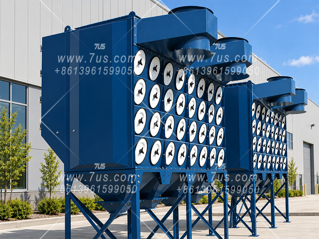
Integrated Cartridge Collectors for Welding Fumes

Select an integrated collector to suit the required airflow, simultaneous welding load and filtration needs. The equipment below illustrates different configurations.

20,000 m³/h INTEGRATED UNIT20,000 m³/h integrated cartridge dust collector for welding fume extraction.
CORRESPONDING DRAWINGCorresponding equipment drawing for the 20,000 m³/h unit. Click to enlarge.
FILTRATION AND DUST COLLECTION OPTIONS

EHI-2 with HEPA and Two Extraction Arms

Compact equipment example
EHI-2 integrated unit equipped with HEPA filtration and two extraction arms.

  • Capture at the welding position: two extraction arms allow the hoods to be positioned close to the welds.
  • HEPA filtration: an additional final filtration stage follows the primary cartridge filters.
  • Drawer or small hopper: for welding applications with low collected dust quantities, these options can replace a conventional large hopper to reduce equipment height and cost. Smaller containers require more frequent emptying.
  • Conventional large hopper: provides greater collection capacity and longer intervals between emptying where space and budget allow.

Explore More All-in-One Dust Collectors

These are equipment examples. Explore our all-in-one dust collector range, including integrated cartridge configurations for welding fume extraction.

View All-in-One Collectors ↗
04

Collector Selection for Higher-Airflow Systems

For multiple welding stations or robotic cells, choose the central collector according to the combined airflow, fume characteristics and workshop layout.

CENTRALIZED WELDING FUME COLLECTION

A Central Collector for the Workshop

System layout example
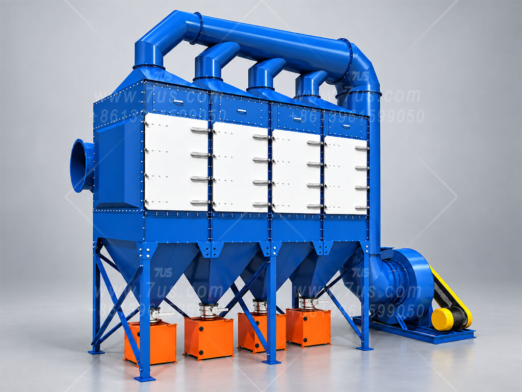
Illustrative arrangement of a centralized welding fume collection system.

Capture devices at the welding stations or robotic enclosures connect through branch ducts to a shared main duct. The central collector treats the combined fume-laden airflow.

  • Airflow for simultaneous operation: combine the requirements of the capture points expected to operate at the same time, and account for airflow through any branches that remain open.
  • Collector configuration: select downflow or vertical cartridge filtration, or a suitable wet collection system, according to the actual application.
  • Fan and ductwork: match the fan to the required airflow and total resistance of the capture devices, ducts and collector.
  • Space and maintenance: allow access for filter servicing or wet-system maintenance, dust removal and routine inspection.
05

Oil Mist Pretreatment and Spark Mitigation

Where welding fumes contain oil mist or carry hot sparks, add suitable upstream treatment to help protect the cartridge filters.

POWDER INJECTION FOR OILY WELDING FUMES

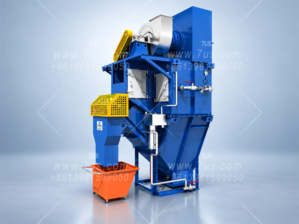
Powder Injection Unit

For fumes containing oil mist, a powder injection unit introduces a suitable conditioning powder into the extraction duct. Lime powder, talc or another compatible inert powder can be selected for the application to help reduce oily deposits and filter blinding.

Powder Injection: Installation and Operating Principle

The powder is injected upstream of the cartridge collector, mixes with the incoming fumes and forms a conditioning layer on the filters. The illustrated dimensions are layout references for this arrangement.

SPARK ARRESTORS UPSTREAM OF THE COLLECTOR

Hot welding sparks entering the collector can ignite accumulated material and damage the filter cartridges. An upstream spark arrestor helps reduce this risk.

Baffle Spark Arrestor

Internal baffles change the airflow direction to intercept hot particles and help reduce sparks reaching the cartridge collector.

View Spark Arrestor ↗

Centrifugal Spark Arrestor

A centrifugal arrangement creates swirling airflow to separate hot particles and promote spark cooling upstream of the collector.

View Spark Arrestor ↗

Spark arrestors help reduce ignition sources; they do not guarantee that all sparks are eliminated. Select the arrangement as part of the overall system fire-risk assessment.

06

Selection Information, FAQs and Enquiry

Send us your welding process, workstation details and workshop layout so we can recommend a suitable centralized welding fume extraction arrangement.

Information for System Selection

  • Process and materials: manual or robotic welding, welding method, workpiece materials and any surface oil or coatings.
  • Workstations: total number of stations and the maximum number operating at the same time.
  • Extraction method: extraction arms, overhead hoods or welding enclosures. For robotic cells, provide enclosure dimensions, openings and hood arrangement.
  • Workshop layout: station positions, proposed collector location, duct routes and available installation space.
  • Oil mist and sparks: describe any oily fumes or hot particles so upstream pretreatment can be considered.
  • Utilities and discharge: supply voltage and frequency, compressed-air availability, and whether filtered air will be exhausted outdoors or considered for indoor return.

The airflow guidance for manual welding extraction arms does not apply directly to robotic welding cells. Each robotic cell requires a separate assessment based on its enclosure, openings and extraction arrangement.

Frequently Asked Questions

Should I choose an integrated or modular collector?

An integrated cartridge collector is a compact option for a smaller manual welding installation. A modular collector provides more flexibility for larger systems. Final selection depends on simultaneous airflow, fume loading, duct resistance and installation space.

Can HEPA filtration be added?

A secondary HEPA filtration stage can be considered where the project requires it. Please tell us your discharge requirements and whether indoor air return is planned so the complete arrangement can be reviewed.

Can the system be expanded later?

Tell us the expected future workstation count at the enquiry stage. Collector capacity, fan duty, main duct size and connection points can then be considered for the planned expansion.

Can robotic welding cells use the same airflow allowance as manual stations?

Robotic enclosures and overhead hoods require their own airflow assessment. Send the enclosure dimensions, opening sizes, welding process and layout rather than selecting solely by the number of robots.

Discuss Your Welding Fume Extraction Project

Send workshop photos, a layout sketch and the information above. We can discuss the extraction arrangement, collector configuration and equipment supply for your project.