
 Click to enlarge
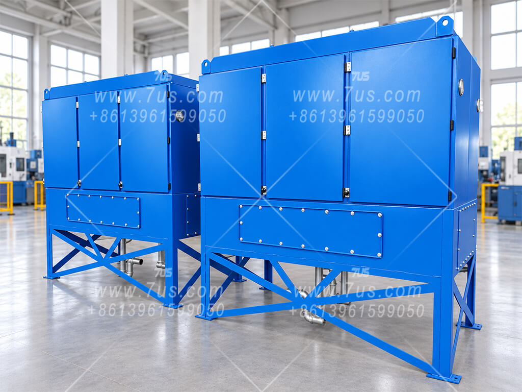
Manufactured Collector Views
Front access doors provide access to the filter elements. Coalesced liquid drains from the bottom outlet, while differential pressure gauges help monitor filter resistance.
Collect cutting-fluid and coolant mist from multiple machining stations through a shared duct system. Coalescing mesh prefilters and fiberglass V-bag filters capture liquid droplets, which drain to a collection outlet.
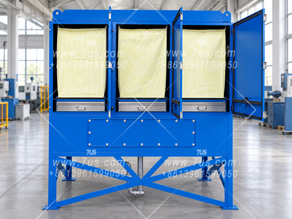
Centralized oil mist collection for multiple machining stations. Select the collector and fan to match the required extraction airflow, duct resistance and coolant mist load.
Click to enlargeFront access doors provide access to the filter elements. Coalesced liquid drains from the bottom outlet, while differential pressure gauges help monitor filter resistance.
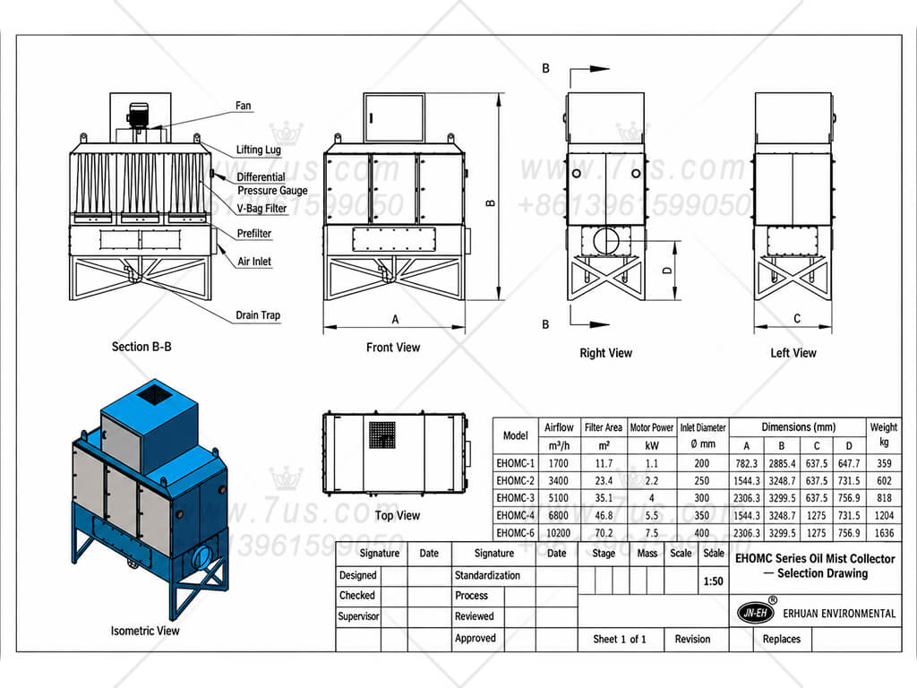 View selection drawing
Reference models EHOMC-1, -2, -3, -4 and -6 cover airflow from 1,700 to 10,200 m³/h. The drawing lists filter area, motor power, inlet size and overall dimensions. Final selection and layout are confirmed for your project.
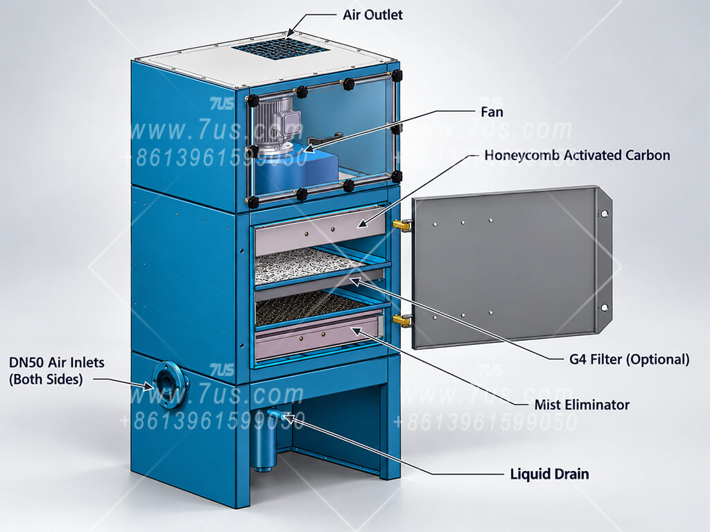
Smaller oil mist collectors and additional filtration stages can be designed to suit the available space, extraction airflow and mist characteristics. The illustrations below show different design concepts; filter arrangements are selected for each application.
 Click to enlarge
A smaller cabinet with an integrated fan and accessible filter trays can be developed for lower airflow requirements. This design concept shows a mist eliminator, an optional G4 filter and an activated carbon stage. Filter media and inlet connections are confirmed for the intended process.
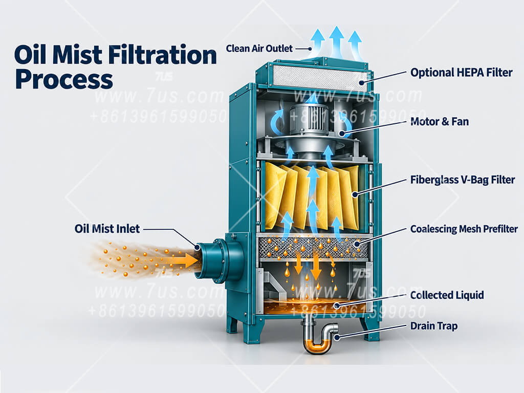 View filtration process
The mesh prefilter coalesces droplets for drainage, and fiberglass V-bag filters capture remaining mist. An optional HEPA final stage can be added for finer particle filtration. The illustration explains the process; the final equipment arrangement is project-specific.
Designed for liquid mist generated by machining with cutting oils or coolants. Suitability depends on the fluid, operating conditions and contaminants carried into the extraction system.
Turning, milling, drilling and wet grinding can generate cutting-fluid or coolant mist. Typical projects include CNC machining cells, precision component production and bearing or gear machining.
A shared duct system can connect multiple machine enclosures to one collector. Extraction airflow is selected according to each machine's requirements and how many machines operate at the same time.
Provide the cutting-fluid type and process details so we can assess the appropriate filter arrangement.
The collected liquid must remain able to coalesce and drain under operating conditions. Grease or other contaminants that solidify, cake or form sticky deposits can block the mesh and filter media; this collector is not intended for those conditions.
High solid-particle loading, elevated temperatures or mixed contaminants require a separate application review. The standard mist filtration arrangement does not provide dedicated treatment for gases or vapors.
Optional HEPA filtration adds a final particle filtration stage. Any indoor air return must be assessed for the actual process and applicable requirements. Reuse of drained liquid depends on its condition and the machining process.
Send us your machining process and extraction requirements. We can propose a collector configuration and confirm connections, layout and equipment scope for your project.
Collector size, filter arrangement, connections, drainage and access clearances can be adapted to your installation.
EHOMC identifies the product series. Final dimensions, fan duty and filter configuration are confirmed in the project proposal and drawing.
Please provide the information available:
If airflow is not yet known, send machine details, enclosure dimensions and a layout sketch or photographs for review.