
Fan-integrated units
Cyclone separator and extraction fan combined in one assembly.
From cyclone units with integrated fans to standalone separators and parallel cyclone assemblies, we configure the equipment around your airflow and installation needs. Cyclone units with cartridge filtration are also available for smaller woodworking applications.
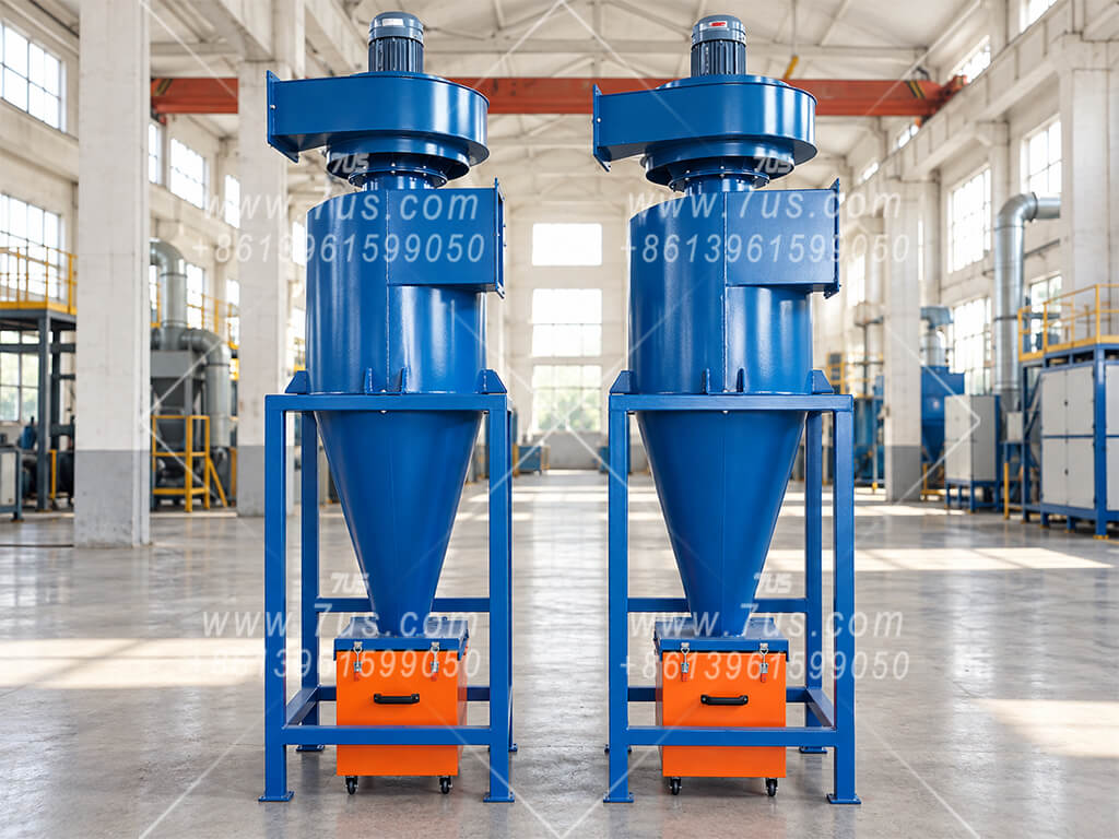
Cyclone separator and extraction fan combined in one assembly.
Cyclone bodies supplied for connection to an external extraction system.
Multiple cyclone bodies operate in parallel above a shared hopper.
Combined separation and filtration for smaller woodworking applications.
The cyclone body, extraction fan, support frame and collection bin form one equipment assembly. The examples below show a top-mounted fan arrangement.
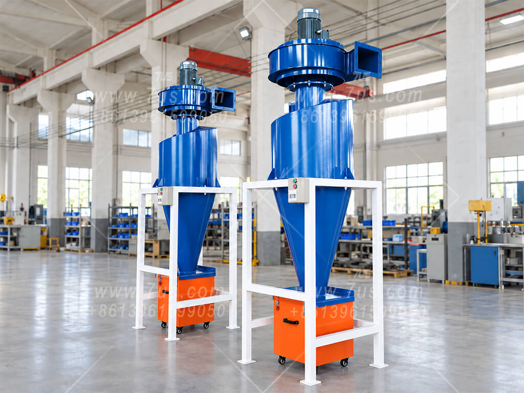
The fan is installed above the cyclone body. Fan airflow and pressure are selected together with the cyclone and the connected duct system.
The side inlet connects to the dust extraction duct. Inlet position, fan discharge direction and connection sizes are confirmed against the installation layout.
Separated material is collected in the bin beneath the cone. Bin capacity and access for emptying are considered alongside the available space and material load.
Confirm the required airflow, material being collected, available installation height and power supply so the equipment arrangement can be specified.
Fan-integrated and filtered units are different configurations. The equipment shown here combines a cyclone and fan. For woodworking units with additional cartridge filtration, see Section 04.
These cyclone separators are supplied without an integrated fan. They connect to an external extraction system, with the fan, ductwork and collection arrangement specified for the application.
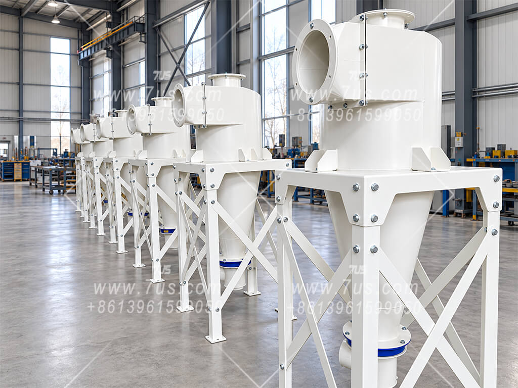
Cyclone bodies with support frames and flanged connections for integration into an external extraction system. Inlet, outlet and discharge connections follow the project layout.
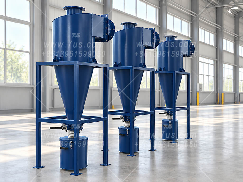
A cyclone separator, support frame and collection bin supplied together. The extraction fan is installed separately; space below the cone is arranged for bin access and emptying.
The system fan provides the airflow through the cyclone. Fan selection takes account of the cyclone, ductwork and any additional equipment in the system.
Connection sizes, inlet direction, support height and access space are confirmed against the site layout and the equipment being served.
The discharge connection and collection arrangement are specified for the material load and handling method. Collection bins are one available configuration.
For selection: Provide the required airflow, material description, existing fan information, duct connections and available installation space.
Multiple cyclone bodies are connected in parallel above one shared hopper. The total airflow is divided between the individual cyclones, while separated material collects in the common hopper below.
Four cyclone bodies, each selected for 10,000 m³/h, form an assembly with a total design airflow of 40,000 m³/h. This is a configuration example; final selection and branch airflow distribution are confirmed for the project.
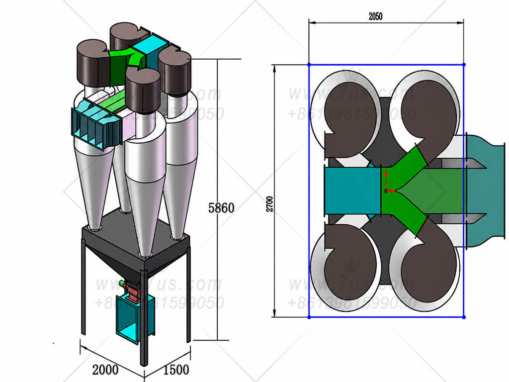
The layout shows four cyclone bodies and a common hopper. Dimensions shown belong to this illustrated arrangement and are not standard dimensions for every assembly.
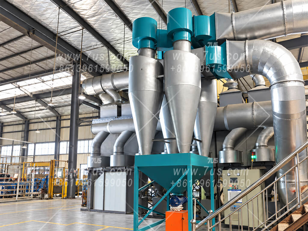
Site example showing parallel cyclone bodies, connecting ductwork and the collection arrangement. The installation photo illustrates the structure; its airflow is not specified here.
The inlet ductwork distributes the incoming air between the cyclone bodies. The cyclones operate side by side, rather than treating the same air in successive stages.
Separated material from the cyclone bodies falls into the common hopper. The outlet and discharge equipment are configured for the material and handling requirements.
Cyclone count, individual capacity, duct connections and support structure are selected together to suit the total airflow and available space.
Designed primarily for smaller-airflow woodworking applications, this configuration combines a cyclone separator, extraction fan and cartridge filter in one assembly. It adds a filtration stage after cyclone separation.
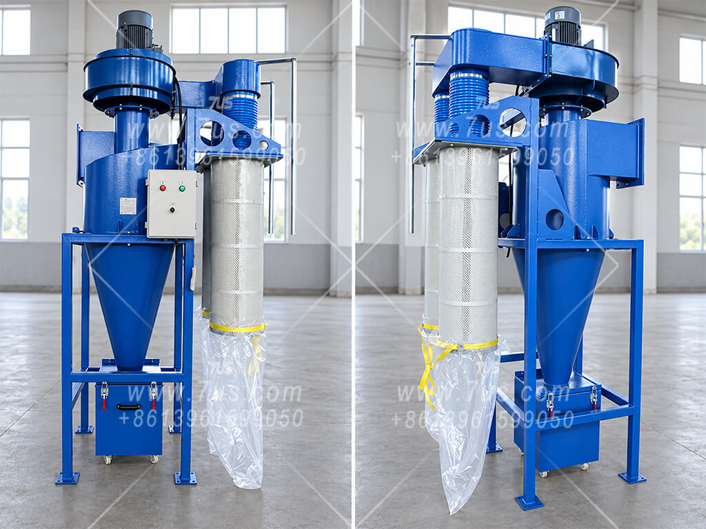
Workshop views showing the cyclone body, integrated fan and side-mounted cartridge filter. A bin collects material below the cyclone, with a separate collection bag beneath the filter.
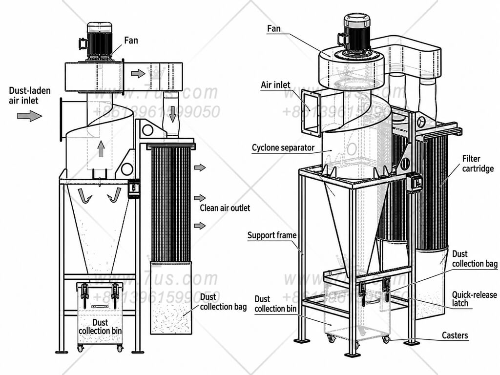
Air passes through the cyclone first, then through the fan to the cartridge filter. The drawing shows the separate collection points below the cyclone and the filter.
The cyclone separates wood chips and a portion of the dust from the incoming air. Separated material falls into the collection bin below.
Air leaving the cyclone passes through the fan to the side-mounted cartridge filter, which captures additional dust before the air exits through the filter media.
The cyclone bin and the bag beneath the cartridge filter provide separate collection points. Leave suitable access for emptying and filter maintenance.
For woodworking applications. Specify the machine or process, required airflow, type of wood dust or chips, and available installation space. Fan selection, filter specification and collection capacity are confirmed for the project.
A cyclone can serve as the first collection stage before a separate dust collector. It removes a portion of the incoming material, while the downstream equipment treats the remaining dust.
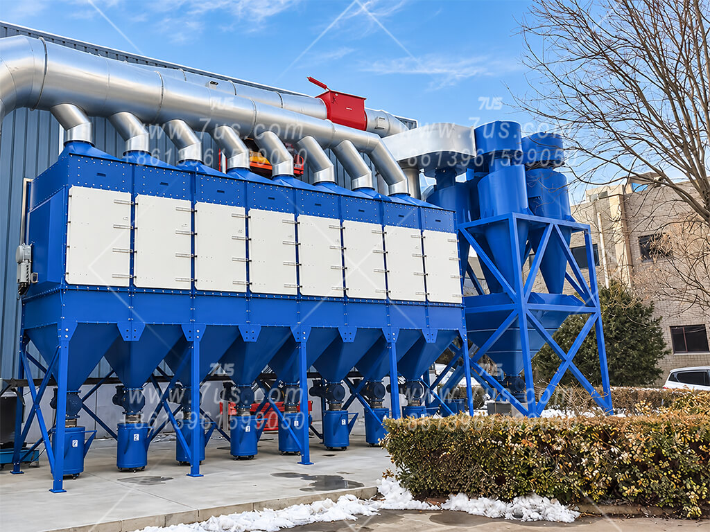
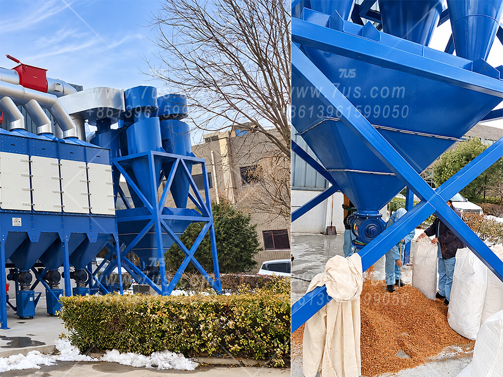
Separating larger particles ahead of the final collector can reduce the amount of material reaching its filters. The benefit depends on the particle size distribution and the cyclone selection.
Cartridge, baghouse or wet collection equipment can be considered according to the material and process. The complete system is selected for the required airflow and outlet air quality.
The fan must be selected for the required airflow and the resistance of the full system, including the cyclone, connecting ducts and downstream collector.
Allow access to each collection point and to the downstream equipment for emptying, inspection and maintenance.
Selection depends on the dust. Cyclone separation performance varies with particle size and operating conditions. Where fine-particle control is required, the downstream collection stage is an important part of the system design.
Our cyclone dust collectors are custom-built around your process, material and installation layout rather than a fixed model range. The options below are discussed during project selection; availability depends on the selected configuration.
Airflow is only the starting point. Particle size, material density, dust loading and operating conditions also affect cyclone selection. Dimensions, pressure drop and fan power are confirmed for the proposed configuration.
Some chemical production processes generate moist, acidic dust that can exceed the corrosion resistance of conventional metal construction. For suitable applications, we manufacture cyclone separators from polypropylene (PP) sheet. Material suitability is confirmed against the chemical composition, concentration and operating temperature.
The swirling airflow separates moist acidic particles by centrifugal action. The separated material travels down the inner wall into a plastic collection vessel below the cyclone. This vessel contains PP polyhedral hollow-ball packing.
An optional alkali dosing system can be fitted to the collection vessel to neutralize the collected acidic liquid, according to process requirements.
Structural pressure limit: For our PP designs, the allowable pressure differential across the wall of an individual cyclone body is typically no more than 4,000 Pa, subject to the project design. This is a structural limit, not the airflow pressure drop through the cyclone.
Send your process details, site photos or a layout drawing. We can discuss a suitable cyclone arrangement and prepare a project-specific quotation.
Request cyclone selection & quotation